Rotary device

A technology of rotating devices and rotating shafts, which is applied in the direction of electromechanical devices, driving devices, feeding devices, etc., can solve the problems of time-consuming rotating devices and difficulty in ensuring the coaxiality of rotating motors, and achieve the goal of ensuring coaxiality and efficient assembly operations Effect

Active Publication Date: 2012-08-08
SANKYO SEISAKUSHO
View PDF4 Cites 5 Cited by
  • Summary
  • Abstract
  • Description
  • Claims
  • Application Information

AI Technical Summary

Problems solved by technology

As a result, there is a problem that it is difficult to ensure the coaxiality of the rotor and the stator in the rotating electric machine
In addition, there is a problem that it takes time to assemble the rotating device due to the large number of parts.

Method used


Image

  • Rotary device
  • Rotary device
  • Rotary device

Examples


Embodiment Construction

[0020] Hereinafter, embodiments of the present invention will be described with reference to the drawings.

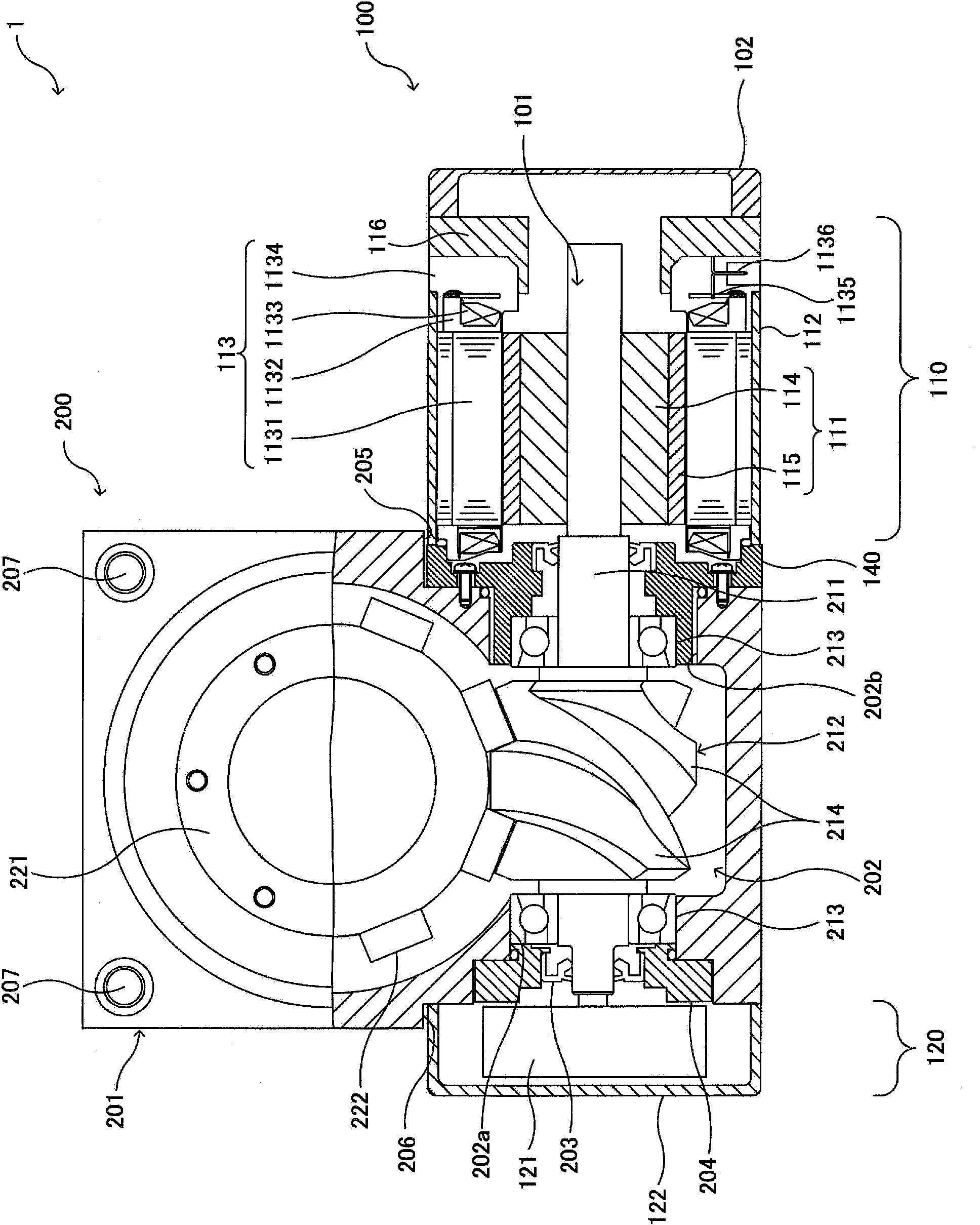
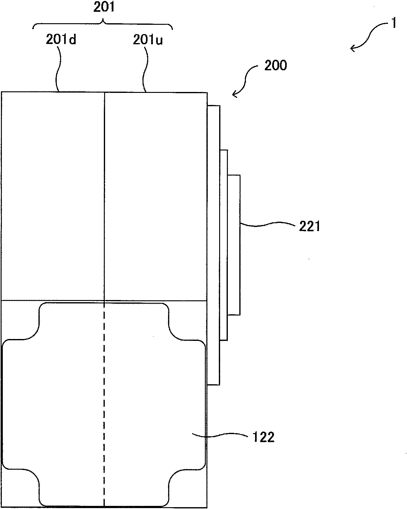
[0021] First, use figure 1 and figure 2 The overall structure of the rotating device as one embodiment of the present invention will be described. figure 1 It is a vertical cross-sectional view showing the overall structure of a rotating device as an embodiment of the present invention. figure 2 It is a side view showing the overall structure of the rotating device as one embodiment of the present invention, viewed from the encoding unit side.

[0022] like figure 1 As shown, the rotary device 1 integrally includes a motor 100 as a rotary electric machine and a speed reducer 200 . The motor 100 has a motor electromagnetic unit 110 and an encoder unit 120 . A speed reducer 200 is disposed between the motor electromagnetic unit 110 and the encoder unit 120 .

[0023] The motor electromagnetic unit 110 includes a rotor 111 and a stator 113 . The rotor 111 is fixed...


PUM


Abstract

The invention provides a rotary device guaranteeing the axiality of a rotor and a stator of a rotary motor and realizing assembling work of the rotary device efficiently. The rotary device (1) is provided with a motor (100) and a reducer (200). The motor is provided with the rotor (111) and the stator (113). The reducer is provided with an input shaft (211) provided with a roller gear cam (212); and an output shaft (221). The periphery of the output shaft is provided with cam driven pieces (222) clamping with the roller gear cam successively. The output shaft extends along a direction perpendicular to the output shaft. The motor is provided with a rotary shaft (101) fixed with the rotor. The output shaft of the rotary shaft and the reducer are connected coaxially. The motor also includes a bearing support part (140) supporting a bearing (213) and exerting a certain preload to the bearing. The bearing supports the output shaft of the reducer to rotate freely. The rotor is arranged in the bearing support part.

Description

technical field [0001] The present invention relates to a rotary device used as a drive source such as a rotary table device. Background technique [0002] Conventionally, in the field of machine tools, for example, a rotary device including a rotary motor and a reducer has been used as a drive source of a rotary table device serving as a mounting table for workpieces (for example, refer to Patent Document 1). In this rotary device, the rotor of the rotary electric machine is connected to the input shaft of the speed reducer with bolts via a mounting flange. In addition, a roller gear cam is provided on the input shaft of the reducer. In addition, the cam followers provided on the outer periphery of the output shaft engage with the roller cam sequentially, whereby the rotation of the input shaft is decelerated and transmitted to the output shaft. The input shaft and the output shaft are rotatably arranged in the housing so that the axial directions of the respective shafts...

Claims


Application Information

Patent Timeline
Patent Type & Authority Applications(China)
IPC IPC(8): H02K7/10H02K5/16
CPCB23Q5/048B23Q5/46
Inventor 山岸俊幸宫内信和加藤寿尚大石贵司高桥俊树
Owner SANKYO SEISAKUSHO
Why Eureka
Try Eureka