High-frequency communication optical fiber polishing method and polishing device

An optical fiber and communication technology, which is applied in the field of high-frequency communication optical fiber grinding methods and grinding devices, can solve the problems of inability to guarantee the smoothness and smoothness of grinding, affecting the production of the unit, and taking a long time to troubleshoot, so as to solve the problem of optical fiber in the control system. The effect of communication failure, improving the efficiency of grinding and maintenance, and improving stability

Active Publication Date: 2012-08-15
BAOSHAN IRON & STEEL CO LTD
View PDF4 Cites 2 Cited by
  • Summary
  • Abstract
  • Description
  • Claims
  • Application Information

AI Technical Summary

Problems solved by technology

In the prior art, grinding is to pinch the head of the optical fiber by hand, and then keep the vertical posture to repeatedly grind the head of the fiber on the sandpaper. When it is relatively flat visually, insert the smoothed head of the fiber into the fiber to fix it. The plug can be connected to the optical communication receiving end. Due to the rough grinding method, the straightness and smoothness of the grinding cannot be guaranteed, resulting in unstable optical fiber communication. In addition, when the laser control communication is abnormal, the optical fiber head is often repeatedly ground. , Repeated installation and repeated failures, the fault processing time is long, the general grinding time is more than 3 hours, and the faults often occur repeatedly, which seriously affects the production of the unit; other similar control systems using this high-frequency communication optical fiber also often occur. question

Method used


Image

  • High-frequency communication optical fiber polishing method and polishing device
  • High-frequency communication optical fiber polishing method and polishing device
  • High-frequency communication optical fiber polishing method and polishing device

Examples


Embodiment 1

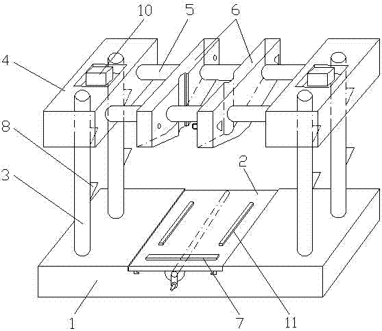
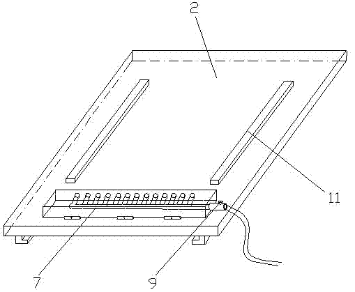
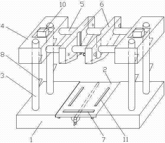
[0026] Such as figure 1 , 2 As shown, a high-frequency communication optical fiber grinding device includes a base 1, a grinding platform 2, a longitudinal guide rod 3, a vertically moving slider 4, a transverse guide rod 5, an optical fiber clamp 6 and a blowing device 7; The longitudinal guide rod 3 is fixed on the base 1, the vertically moving slider 4 is installed on the longitudinal guide rod 3, the moving slider 4 and the longitudinal guide rod 3 form a moving pair, and the longitudinal guide rod 3 is provided with an elastic support piece 8, which moves vertically The slider 4 is supported by the elastic support piece 8 when it is in the upper position; the lateral guide rod 5 is fixed on the moving slider 4, the optical fiber clamp 6 is installed on the lateral guide rod 5, and the lateral guide rod 5 and the optical fiber clamp 6 It constitutes a moving pair; the base 1 is provided with a chute directly below the optical fiber fixture 6, the grinding platform 2 is se...


PUM


Abstract

The invention relates to the field of communication optical fiber polishing, in particular to a high-frequency communication optical fiber polishing method and a polishing device. The high-frequency communication optical fiber polishing method comprises the following steps that: two pieces of abrasive paper are selected, one piece is coarse abrasive paper, the other piece is high-precision fine grinding paper, an optical fiber is tightly clamped by an optical fiber clamp, the coarse abrasive paper is used for polishing, a spray blowing device is used for spray blowing during the polishing, the end part of the optical fiber is cleaned, the high-precision fine grinding paper is used for polishing, the spray blowing device is used for blowing during the polishing and is aligned with the end part of the optical fiber for carrying out spray blowing cleaning, and the high-frequency communication optical fiber polishing is completed. The polishing is carried out after the optical fiber is positioned by the clamp and the straightness is controlled, the spray blowing device is used for blowing off fragments during the polishing, and the polishing stability is improved; and in addition, the combination of two kinds of abrasive paper is utilized for polishing, the finish degree is improved, visually visible optical fiber end paraboloids and saw tooth surfaces after the original polishing are eliminated, and the frequently generated optical fiber communication fault problems of a control system are solved.

Description

technical field [0001] The invention relates to the field of communication optical fiber repairing and polishing, in particular to a high-frequency communication optical fiber repairing method and a repairing device. Background technique [0002] Many welding machines used in cold rolling use laser welding machines. The high-frequency communication optical fiber is used as the communication medium between the terminal control system of the welding machine and the high-frequency drive control system. This optical fiber is a special communication for high-frequency communication. Before the optical fiber is used, its optical fiber head must be polished. In the prior art, grinding is to pinch the head of the optical fiber by hand, and then keep the vertical posture to repeatedly grind the head of the fiber on the sandpaper. When it is relatively flat visually, insert the smoothed head of the fiber into the fiber to fix it. The plug can be connected to the optical communication...

Claims


Application Information

Patent Timeline
Patent Type & Authority Applications(China)
IPC IPC(8): B24B19/22
Inventor 陈杰钱高展潘维平
Owner BAOSHAN IRON & STEEL CO LTD
Why Eureka
Try Eureka