
Counting machine

A point and rack technology, applied in packaging automatic control, packaging, packaging protection, etc., can solve the problems of easy-to-leak gloves, short service life of air pressure clamps, etc., and achieve the effect of easy use, stable grasping, and convenient packaging.

Inactive Publication Date: 2012-08-15
ZHANGJIAGANG PIONEER AUTOMATION MACHINERY EQUIP
View PDF6 Cites 6 Cited by
  • Summary
  • Abstract
  • Description
  • Claims
  • Application Information

AI Technical Summary

Problems solved by technology

The currently used counting machine uses air pressure clamps to grab gloves. The air pressure clamps have a short service life and are easy to miss the gloves, and they also need compressed air to drive.

Method used


Image

  • Counting machine
  • Counting machine
  • Counting machine

Examples


Embodiment Construction

[0014] The point machine of the present invention will be further described in detail through specific embodiments below.

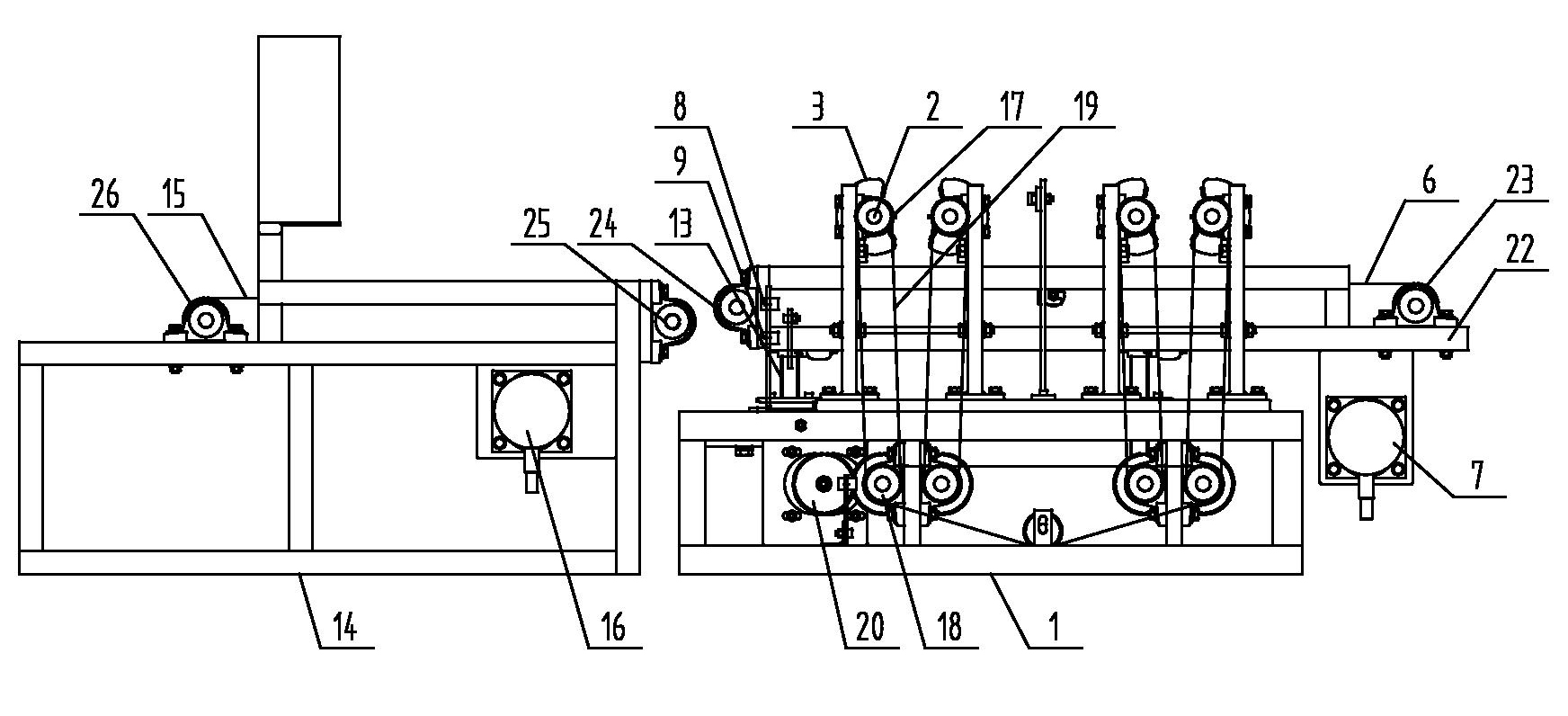
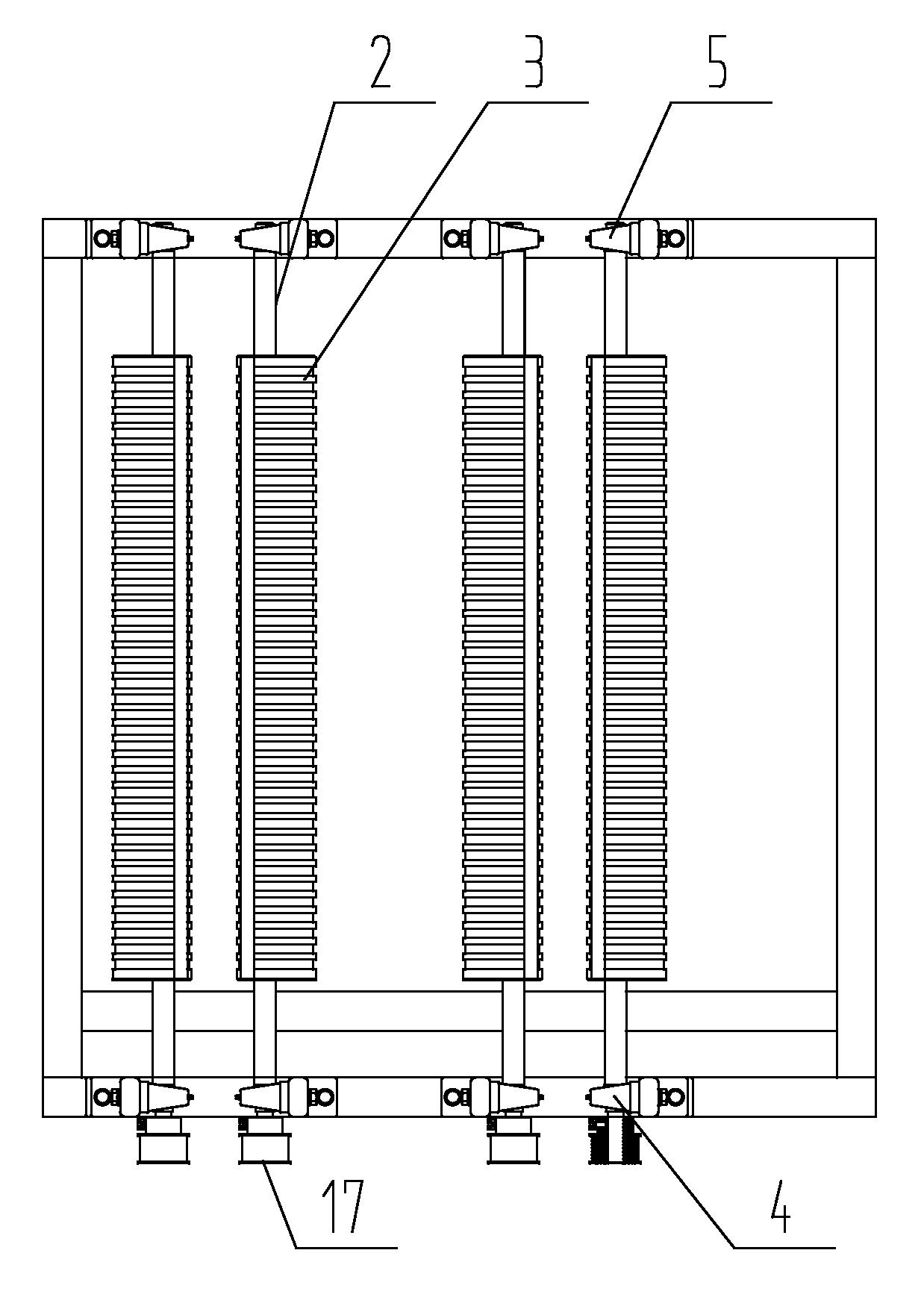
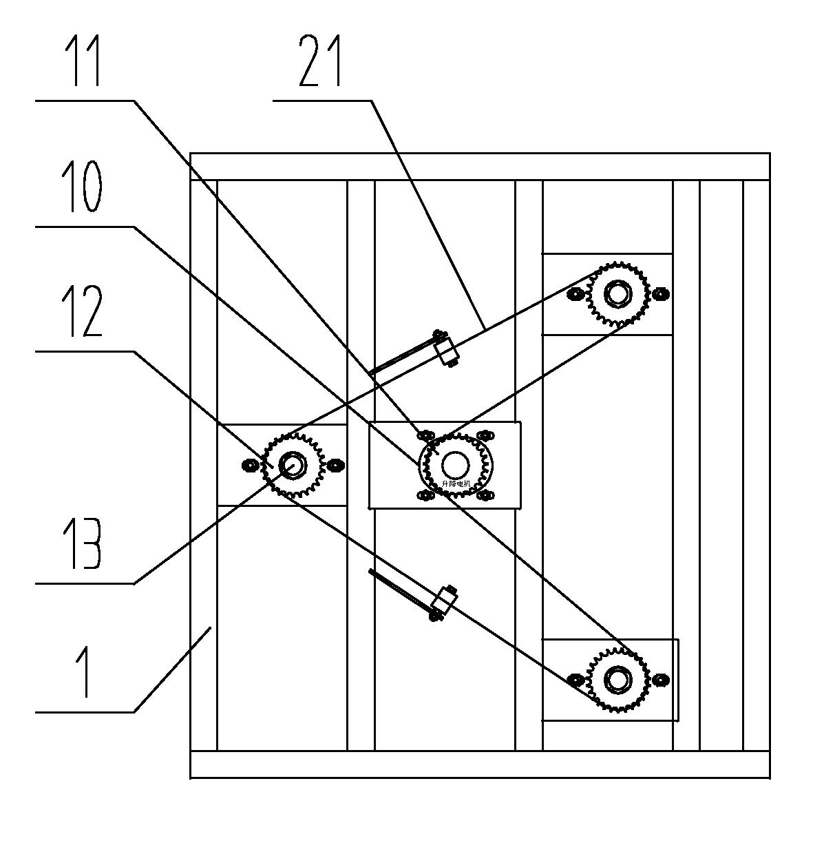
[0015] Such as figure 1 As shown, a counting machine includes a frame 1, and the frame 1 is provided with at least one group of grabbing mechanisms. In this embodiment, two groups of grabbing mechanisms are included, such as figure 2 As shown, each group of grabbing mechanisms includes: two mutually parallel rotating shafts 2 that are movably arranged in the frame 1, and each rotating shaft 2 is respectively connected with a rotating drive device arranged on the frame 1, as Looking down from the top of the grab mechanism, the rotary drive device drives the two rotary shafts 2 to rotate in different directions, and if viewed from the bottom of the grab mechanism, the rotary drive device drives the two rotary shafts 2 to rotate in different directions. Rotating outwards, several cams 3 are arranged on the two rotating shafts 2 respectively, and the cams 3...


PUM


Abstract

The invention relates to a counting machine which comprises a rack, wherein the rack is provided with at least one group of fetching mechanisms; each fetching mechanism comprises two mutually parallel rotary shafts arranged in the rack; each rotary shaft is respectively connected with a rotary driving device arranged on the rack; the driving device drives the two rotary shafts to rotate inwards in opposite directions; the two rotary shafts are respectively provided with a plurality of cams which are arrayed; the cams on the two rotary shafts are mutually symmetrically arranged; two ends of each rotary shaft are respectively provided with a counting sensor; a platform is arranged below the fetching mechanism; a conveying belt is arranged in the platform; the conveying belt is driven by a conveying motor arranged on the platform; and the rack is also provided with an up-and-down movement driving device which can drive the platform to move up and down along the vertical direction. The counting machine has the advantages of simple structure and long service life, and is convenient to use. Because the cam mechanism is adopted and the cams rotate to fetch gloves, the gloves can be stably fetched, and no gloves are missed. Because compressed air is not required, the cost is low.

Description

technical field [0001] The invention relates to a counting machine used in a glove production line. Background technique [0002] During the production of gloves, the gloves on the hand mold base are hung on the hand mold base after demoulding, then peeled off and counted by the counting machine, and finally packed by workers. The currently used counting machine uses pneumatic clamps to grab gloves. The pneumatic clamps have a short service life and are easy to miss the gloves, and also need compressed air to drive. Contents of the invention [0003] The technical problem to be solved by the present invention is to provide a counting machine that can stably grab gloves, has a long service life and is low in cost. [0004] In order to solve the above problems, the technical solution adopted in the present invention is: a counting machine, comprising a frame, at least one group of grabbing mechanisms is arranged on the frame, and each group of grabbing mechanisms includes: ...

Claims


Application Information

Patent Timeline
IPC IPC(8): B65B57/20B65B35/16
Inventor 钱仁明
Owner ZHANGJIAGANG PIONEER AUTOMATION MACHINERY EQUIP
Learn More