Vacuum sputtering device and use method thereof

A technology of vacuum sputtering and sputtering, which is used in vacuum evaporation coating, sputtering coating, ion implantation coating and other directions, and can solve the problems of poor sputtering effect, air leakage, and poor sealing.

Active Publication Date: 2012-08-15
SHANGHAI HUAHONG GRACE SEMICON MFG CORP
View PDF3 Cites 0 Cited by
  • Summary
  • Abstract
  • Description
  • Claims
  • Application Information

AI Technical Summary

Problems solved by technology

[0005] The problem that the present invention solves is to propose a kind of new vacuum sputtering device and using method thereof, to improve the existing vacuum sputtering device in the process of vacuumizing a certain outlet / entrance cavity, the sealed cavity (has reached vacuum) Degree requirements) due to poor sealing, there will be air leakage, thereby avoiding the problem of poor sputtering effect

Method used


Image

  • Vacuum sputtering device and use method thereof
  • Vacuum sputtering device and use method thereof
  • Vacuum sputtering device and use method thereof

Examples


Embodiment Construction

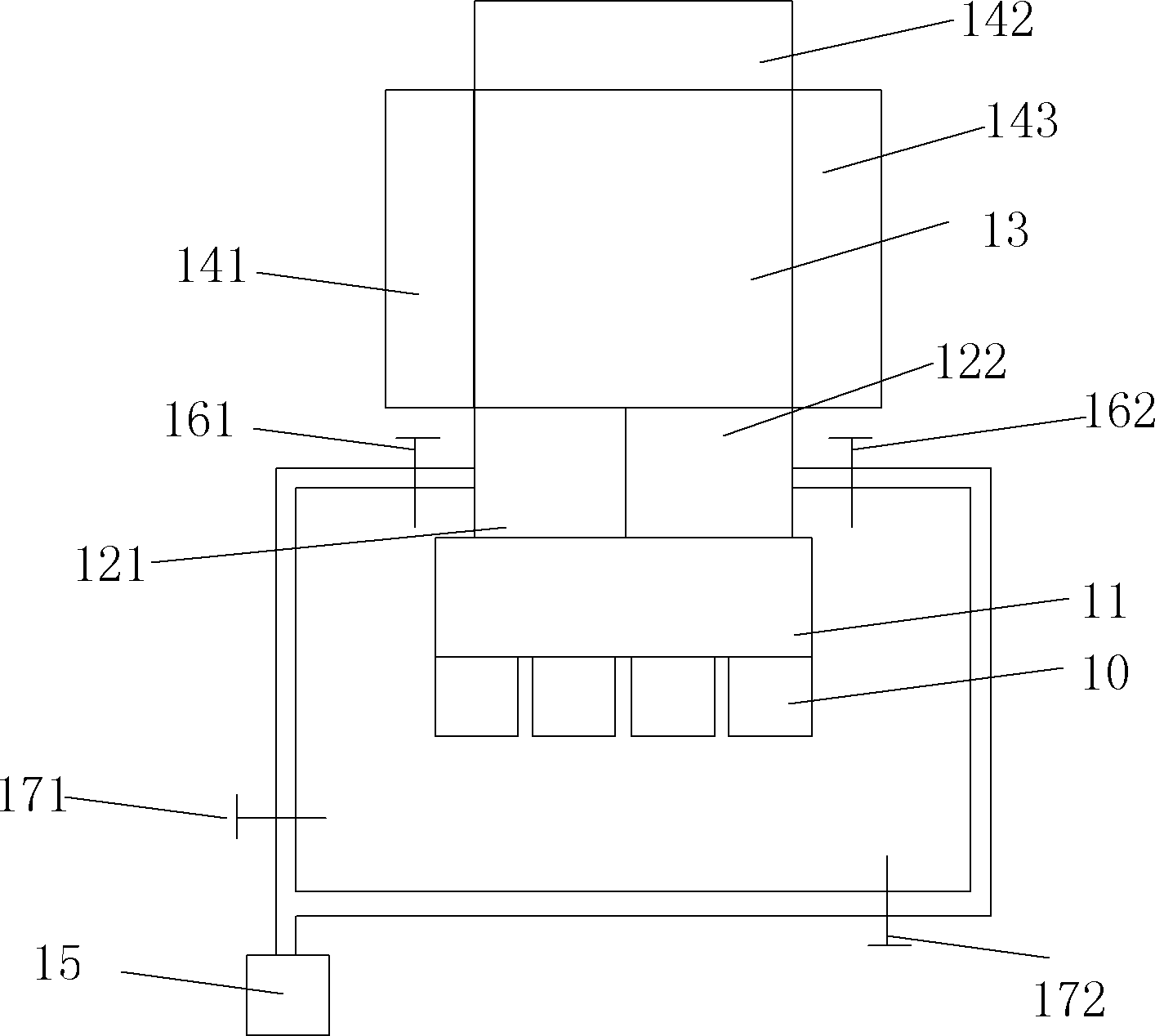
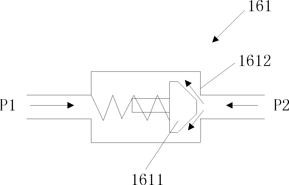
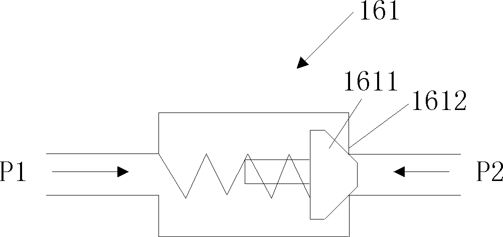
[0034] As mentioned in the background technology, the vacuuming process of multiple exit / entry chambers is realized by one vacuum pump. Therefore, when the vacuum degree of a certain cavity reaches a certain requirement, the valve arranged between the vacuum pump and the exit / entry chamber is closed, and the other chambers are closed. The chamber is still being evacuated or undergoing a transfer process. However, due to the long-term use of the valve or the corrosion of the inert plasma gas in the sputtering environment, the gasket of the chamber whose vacuum degree reaches a certain level may be worn out, and the seal may not be good, resulting in the entry of external gas and gas backflow. To solve this problem, the present invention proposes that at least two airflow isolation devices are arranged between each of the outlet / inlet chambers and the vacuum pump, at least one of which can automatically prevent gas from flowing into the outlet / inlet chambers. In this way, the qu...


PUM


Abstract

The invention provides a vacuum sputtering device comprising at least two outlet / inlet cavities, a transmitting cavity, a sputtering cavity and a vacuum pump, wherein a first airflow isolating device and a second airflow isolating device are at least arranged between the outlet / inlet cavities and the vacuum pump, and at least one of the first airflow isolating device and the second airflow isolating device can automatically prevents gas from flowing into the outlet / inlet cavities. Furthermore, the invention further provides a use method of the vacuum sputtering device. After the technical scheme of the invention is adopted, the air leakage of the cavities which are sealed and reach the vacuum degree requirement caused by imprecise seal when some outlet / inlet cavities are vacuumized by the conventional vacuum sputtering device can be improved, and the problem of poor sputtering effect can be further avoided.

Description

technical field [0001] The invention relates to the field of semiconductor manufacturing, in particular to a vacuum sputtering device and a using method thereof. Background technique [0002] In the existing semiconductor manufacturing process, the completion of many structures involves metal sputtering, such as metal interconnection structures. The sputtering process is generally completed by bombarding the target with inert gas, so its working environment requires vacuum conditions. When sputtering is required, first place the substrate to be sputtered in the front chamber under atmospheric pressure, and then move the substrate to be sputtered from the front chamber to the substrate holder of the load lock , then close the exit / entry chamber and apply a vacuum to transfer it through the transfer chamber into the respective sputter chamber. In the prior art, in order to improve efficiency, a plurality of smaller volume exit / entry chambers are generally set, and the exit / e...

Claims


Application Information

Patent Timeline
Patent Type & Authority Applications(China)
IPC IPC(8): C23C14/34C23C14/56
Inventor 张杰解毅何雅彬赵洪涛王喆马东吴奇昆沈瑜俊孙亭
Owner SHANGHAI HUAHONG GRACE SEMICON MFG CORP
Why Eureka
Try Eureka