
Patsnap Eureka
For R&D, Patsnap Eureka makes reading and utilizing patents & technical documents easy.
Patsnap Eureka AIR
Designed for self-driven R&D workflows. Generate viable solutions, solve complex R&D challenges, empower your innovation with AI.

Patsnap Eureka Materials
Designed for material experts only. Revolutionize your material R&D, from search, analyze, to developing new materials.

TechResearch
Generate reliable direction feasibility study reports for your R&D in just a few steps.

TechSeek
Discover and master advanced knowledge NOW. Basics, ideas, possibilities, all at once.

TechMind
As an expert in R&D Theories, TechMind can generates customized viable solutions instantly.

TechRisk
Analyze your overall solution with one click, know your potential R&D risks in advance.

TechMonitor
Get weekly tech updates, stay abreast of the latest tech innovations and key insights.
Self-lubricating bearing for hydraulic steel gate
A technology of self-lubricating bearings and gates, which is applied in the direction of sliding contact bearings, rotating bearings, bearings, etc., to reduce matrix wear, increase service life, and reduce maintenance costs
- Summary
- Abstract
- Description
- Claims
- Application Information
AI Technical Summary
Problems solved by technology
Method used
Image

Examples
Embodiment 1
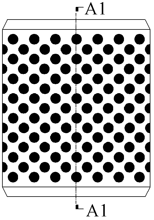
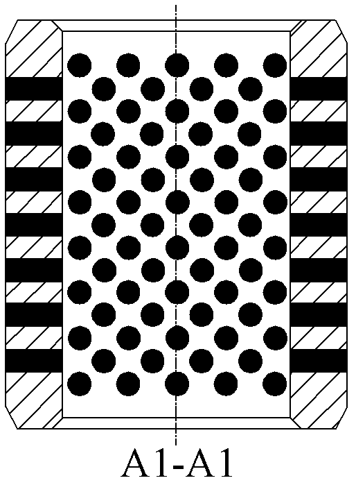
[0039] Such as Figure 6 and Figure 7 As shown, this embodiment discloses an inlaid self-lubricating bearing for hydraulic steel gates, which is mainly composed of a tubular matrix 3 , a solid lubricant 5 , a thrust spring 6 and a bearing pad type fixed shell 2 .
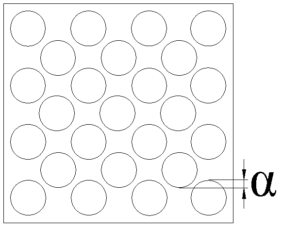
[0040] Such as Figure 13 and Figure 14 As shown, the tubular base 3 is used to be sleeved on the journal 4 , and a plurality of pre-drilled holes 8 are distributed on the tubular base 3 . Similarly, all the pre-opening holes 8 are staggered along the direction of rotation, and there should be a certain degree of overlap α between the pre-opening holes 8 in the axial or radial direction, so as to ensure that the solid lubricant 5 covers the entire sliding direction and form a complete solid lubricating film.
[0041] The tubular matrix 3 of the inlaid self-lubricating bearing can be selected from a wide range of materials, mainly including cast iron, tin bronze, high-strength brass, stainless steel, tin-antimo...
Embodiment 2
[0069] Such as Figure 16 and Figure 17 As shown, this embodiment discloses a powder metallurgy integrally sintered self-lubricating bearing for hydraulic steel gates, which mainly consists of a tubular matrix 3, a solid lubricant 5, a thrust spring 6, a bearing pad type fixed shell 2, and a sealing ring 12 And sealing ring fixing end cover 13 constitutes. The tubular base 3 is used to be socketed and installed on the journal 4. There are a plurality of pre-opened holes 8 distributed on the tubular base 4. The pre-opened holes 8 are sequentially installed with a solid lubricant 5 and a thrust spring 6 from the inside to the outside. The solid lubricant The agent 5 is in clearance fit with the pre-opening hole 8, and the clearance distance is 0.00005m-0.00015m. The outer sleeve of the tubular base 4 is fitted with a bearing pad type fixed shell 2 fixed on the tubular base body 3 by countersunk head screws 9 , and the inner wall of the bearing pad type fixed shell 2 abuts aga...
PUM
| Property | Measurement | Unit |
|---|---|---|
| Gap distance | aaaaa | aaaaa |
Abstract
Description
Claims
Application Information
 - R&D Engineer
- R&D Manager
- IP Professional
- Industry Leading Data Capabilities
- Powerful AI technology
- Patent DNA Extraction
Browse by: Latest US Patents, China's latest patents, Technical Efficacy Thesaurus, Application Domain, Technology Topic, Popular Technical Reports.
© 2024 PatSnap. All rights reserved.Legal|Privacy policy|Modern Slavery Act Transparency Statement|Sitemap|About US| Contact US: help@patsnap.com