Connection structure of electromagnetic cooker surface

A connection structure and cooktop technology, applied in the direction of furnace/stove top, etc., can solve problems such as appearance defects, difficult production process, long production cycle, etc., and achieve the effects of facilitating production management, eliminating the need for curing time, and improving production efficiency

Active Publication Date: 2012-08-15
MIDEA GRP CO LTD
View PDF5 Cites 1 Cited by
  • Summary
  • Abstract
  • Description
  • Claims
  • Application Information

AI Technical Summary

Problems solved by technology

[0003] At present, the connection between the stove panel and the heating plate in the prior art is generally fixed by glue. In order to prevent the relative position of the panel from changing, it needs to be placed for a certain period of time after the glue is fixed, so that the glue can be cured before it can be put into production. The disadvantages mainly focus on the need for a large amount of silicone glue and long curing time, and the glue needs to be trimmed to achieve a perfect appearance. There are problems such as long production cycle, low production efficiency, serious appearance defects and difficult production process, which need to be improved.

Method used


Image

  • Connection structure of electromagnetic cooker surface
  • Connection structure of electromagnetic cooker surface
  • Connection structure of electromagnetic cooker surface

Examples


Embodiment 1

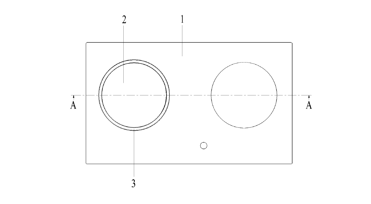
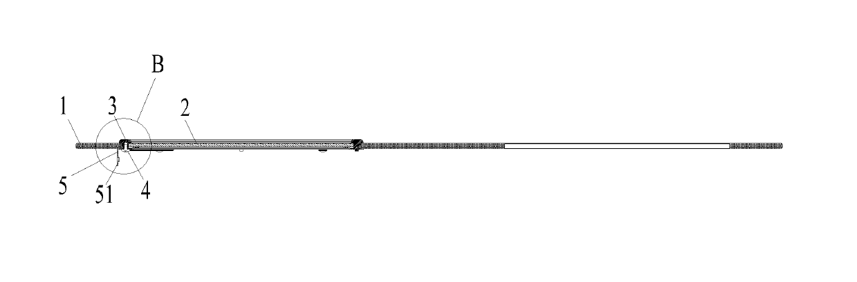
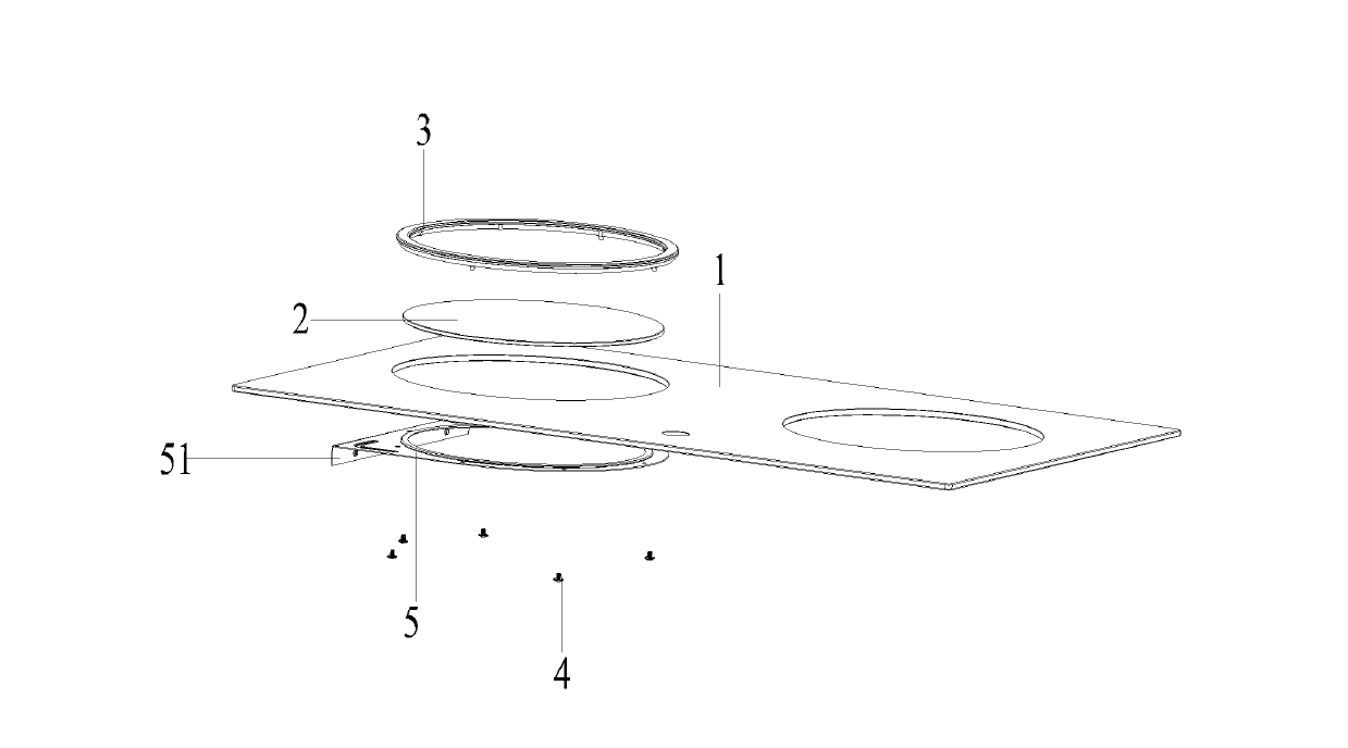
[0025] See Figure 1-Figure 6 , figure 1 It is a top view structural diagram of the connection structure of the electromagnetic cooktop in the embodiment of the present invention; figure 2 for figure 1 Schematic diagram of the cross-sectional structure of the A-A direction of the connection structure of the medium induction cooktop; image 3 It is a schematic diagram of the decomposition structure of the connection structure of the electromagnetic cooktop in the embodiment of the present invention; Figure 4 for figure 2 Enlarged image at B. Figure 5 It is a structural schematic diagram of the decorative ring in the connection structure of the electromagnetic cooktop according to the embodiment of the present invention. Image 6 It is a schematic diagram of the rear structure of the decorative ring in the connection structure of the electromagnetic cooktop according to the embodiment of the present invention.

[0026] The connection structure of the electromagnetic co...

Embodiment 2

[0037] The difference between this embodiment and Embodiment 1 is that the connection structure of the induction cooker surface also includes a sealing gasket, which is arranged on the part where the support contacts the heating plate, the cooker panel and the decorative ring, so as to prevent water from entering the induction cooker. Inside, it's even safer. The heating plate is made of glass-ceramic.

[0038] The upper surface of the decorative ring is provided with a ring-shaped protrusion higher than the heating plate. The ring-shaped protrusion is 8mm higher than the heating plate, which is conducive to placing the pot on the heating plate more accurately, and can also prevent the pot from deviating from the heating position.

[0039] The assembly process of the connection structure of the electromagnetic cooktop provided in this embodiment is as follows:

[0040] Put the heating plate into the decorative ring, and then put the two into the stove panel as a whole, fix th...


PUM


Abstract

The invention discloses a connection structure of an electromagnetic cooker surface. A heating plate and a surface plate are embedded in a clearance between a decorative ring and a bracket, the decorative ring and the bracket are connected via a connector, and the bracket is a ring-shaped bracket. Compared with the prior art, the connection structure of the electromagnetic cooker surface has the advantages that the heating plate and the surface plate are fixed in a physical way, the installation is solid and reliable, no curing time is needed, the mass production can be performed immediately after connection, the production efficiency can be improved greatly, and the onsite production management can be facilitated.

Description

technical field [0001] The invention relates to the field of electromagnetic heating, in particular to a connection structure for an electromagnetic cooktop. Background technique [0002] In today's induction cooker industry, due to the comprehensive consideration of cost, appearance and performance, the heating plate and the cooker panel are connected and used together with panel materials of different materials. For example, in order to consider the convenience and cost of silk screen printing, the cooker panel of the induction cooker is made of tempered glass, but the thermal shock performance of the tempered glass plate cannot meet the heating requirements, so a hole is opened in the middle of the cooker panel, and a cold plate is embedded in the hole. Glass-ceramic plates or ceramic plates with high thermal shock performance are combined into panel components and used in products. [0003] At present, the connection between the stove panel and the heating plate in the ...

Claims


Application Information

Patent Timeline
Patent Type & Authority Applications(China)
IPC IPC(8): F24C15/10
Inventor 邹伟陈光亮黄建辉
Owner MIDEA GRP CO LTD
Why Eureka
Try Eureka