Air conditioner

A technology for air conditioners and evaporators, which is used in air conditioning systems, space heating and ventilation, space heating and ventilation details, etc. Large space and other problems, to achieve the effect of small impact on the overall appearance, reducing the space occupied, and improving the heat exchange effect

Inactive Publication Date: 2012-08-15
四川同达博尔置业有限公司
View PDF12 Cites 8 Cited by
  • Summary
  • Abstract
  • Description
  • Claims
  • Application Information

AI Technical Summary

Problems solved by technology

[0003] However, the condensers and evaporators in the existing cooling and heating window air conditioners mostly adopt a single vertical plate design and blowing arrangement, and the fan in the air conditioner uses an axial fan. The window air conditioner with this structure Although the purpose of adjusting the indoor air can be better achieved, since the condenser and evaporator adopt a single plate design, if the heat exchanger is to meet the actual design requirements, the condenser and evaporator need to be designed more The large heat exchange area makes the heat exchanger take up a larger space; at the same time, the structure of the axial flow fan also takes up a larger space, which makes the window air conditioner larger in size and thicker in lateral dimensions
On the other hand, due to the limited volume of existing window air conditioners, the heat exchange area of ​​the condenser and evaporator is limited to a certain extent. Therefore, in order to make the heat exchange effect of the condenser and evaporator meet the design requirements, it is often necessary to The speed of the fan is large, and as a result, the increase in the speed of the fan leads to an increase in the noise of the air conditioner
Therefore, existing window air conditioners often have defects such as large volume, low heat transfer efficiency, uneven heat transfer, and loud noise.
In addition, when installing a window air conditioner, a large window hole needs to be opened on the wall, which also brings a lot of inconvenience to the installation.

Method used


Image

  • Air conditioner
  • Air conditioner
  • Air conditioner

Examples


Embodiment Construction

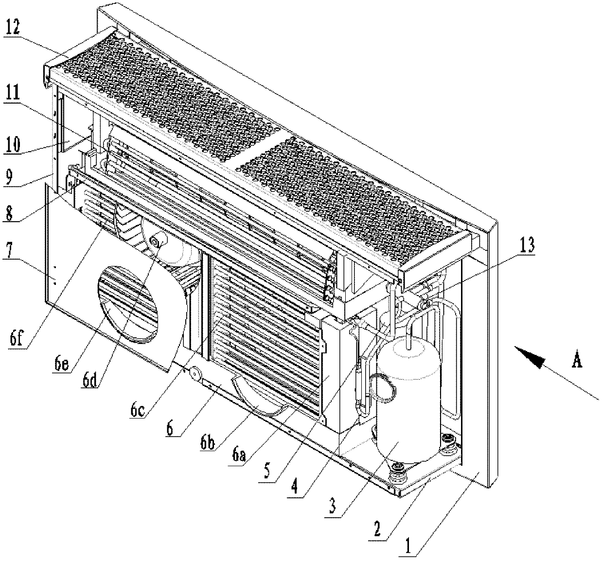
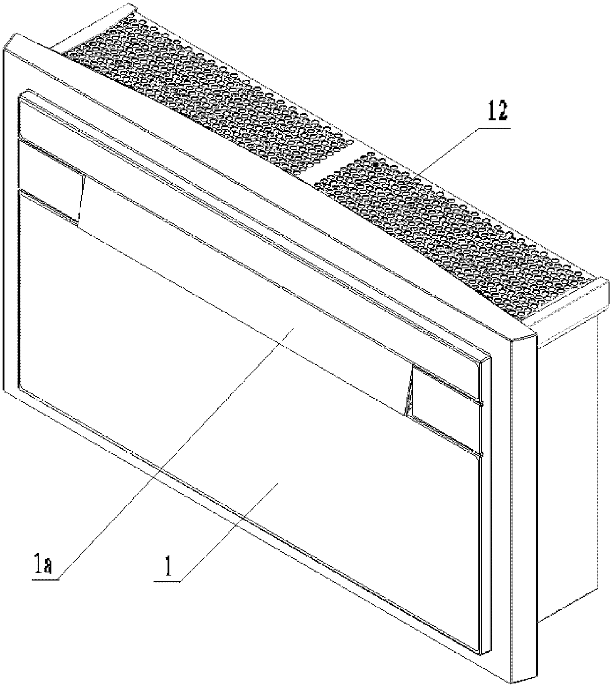
[0025] figure 1 and figure 2 Perspective view of an embodiment of an air conditioner according to the present invention. Such as figure 1 and figure 2 As shown, the air conditioner according to the present invention has a casing and internal components. Wherein, the casing includes: a panel 1, which is positioned at the front of the air conditioner, and is provided with a wind deflector 1a on the panel 1, and the wind deflector 1a is opened and closed by a motor 1b (see Figure 4 ), so that the indoor air can flow in all directions of the indoor space through the air deflector 1a after heat exchange with the evaporator 11; the side plates 9, which are located on both sides of the air conditioner, are used to install and fix the control circuit of the air conditioner Plate 10; rear plate 7, which is located at the rear of the air conditioner; bottom plate 2, which is located at the bottom of the air conditioner, for installing and fixing the panel 1, side plate 9 and rear...


PUM


Abstract

The invention discloses an air conditioner which comprises a shell and an inner assembly positioned in the shell, wherein the shell comprises a panel, a side plate, a rear plate, a bottom plate and an air inlet grating, and the inner assembly comprises a condenser and an evaporator. The air conditioner is characterized in that the air conditioner is positioned indoors and also comprises an air inlet pipe and an air outlet pipe which penetrate through a wall body; outdoor air is introduced into the air conditioner via the air inlet pipe and an air inlet on the rear plate to carry out heat exchange with the condenser; the air subjected to heat exchange is discharged out of a room via the air outlet on the rear plate and the air outlet pipe; the evaporator is a V-shaped heat exchanger and comprises a first evaporator part and a second evaporator part; and the first evaporator part and the second evaporator part are set to form an included angle. The special structure form of the air conditioner has the characteristics of strong process operability, simple structure and small occupied space, is convenient to install and is suitable for various buildings.

Description

technical field [0001] The invention relates to an air conditioner. Background technique [0002] There are many types of existing household air conditioners, which can be divided into integrated units and split units according to the structural form. Split unit air conditioners can be divided into split wall-mounted, split vertical cabinet, split Ceiling-type, etc., all-in-one air conditioners are mainly traditional window-type air conditioners. Since the outdoor unit of the split unit must be installed on the outer wall of the building, it will affect the appearance of the building, while the integrated unit does not have this problem, so it is generally used in places that require high appearance of the outer wall of the building. Window air conditioner. In addition, in the temperate climate zone, the air conditioner is usually required to have both cooling and heating functions, so the cooling and heating heat pump type window air conditioner has a considerable market....

Claims


Application Information

Patent Timeline
Patent Type & Authority Applications(China)
IPC IPC(8): F24F1/00F24F13/30
Inventor 梁玉祥
Owner 四川同达博尔置业有限公司
Why Eureka
Try Eureka