Cross-under type heat pipe structure and manufacturing method thereof

A production method and technology of heat pipes, applied in indirect heat exchangers, lighting and heating equipment, etc., can solve the problems of high vaporization rate and condensation rate, dry burning, dry burning of heat pipes, etc., to reduce thickness, increase contact area, and improve heat conduction efficiency effect

Inactive Publication Date: 2012-08-15
KUNSHAN JUZHONG ELECTRONICS
View PDF8 Cites 3 Cited by
  • Summary
  • Abstract
  • Description
  • Claims
  • Application Information

AI Technical Summary

Problems solved by technology

[0003] With the rapid development of science and technology, the working efficiency of electronic components has been greatly improved, and the heat generation per unit time has also increased a lot. Therefore, when the working fluid in the heat-absorbing section of the heat pipe absorbs such an increase in heat, the working fluid has completely Vaporization, but the vaporization rate of the endothermic section is much larger than the condensation rate of the exothermic section, resulting in the so-called dry out phenomenon in the endothermic section of the heat pipe
In order to solve the above problems, the size of the heat pipe must be increased to increase the volume of the working fluid, but this cannot meet the needs of increasingly thinner electronic components
[0004] On the other hand, in the case where long-distance heat conduction is required, since the moving rate of the gas in the heat pipe is greater than the return rate of the working fluid flowing in the capillary tissue, this speed difference is more obvious in the long-distance heat pipe, resulting in a long-distance heat pipe The dry burning phenomenon is more serious, which is the bottleneck when designing long-distance heat pipes; in addition, because in the whole heat pipe, only the working fluid near the endothermic section and the exothermic section has the phase transition of endothermic evaporation and exothermic condensation In other words, the actual effective working parts of the entire heat pipe are only concentrated on the two ends of the heat-absorbing section and the heat-radiating section, resulting in other parts of the heat pipe not being able to make substantial contributions to the efficiency of heat transfer

Method used


Image

  • Cross-under type heat pipe structure and manufacturing method thereof
  • Cross-under type heat pipe structure and manufacturing method thereof
  • Cross-under type heat pipe structure and manufacturing method thereof

Examples


Embodiment Construction

[0075] The detailed description and technical content of the present invention will be described as follows with the accompanying drawings, but the attached drawings are only for illustration purposes and are not intended to limit the present invention.

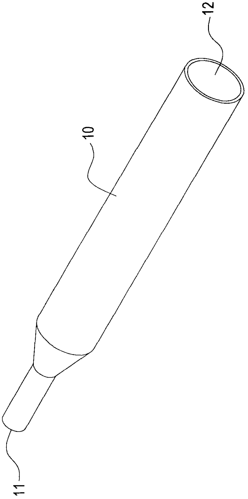
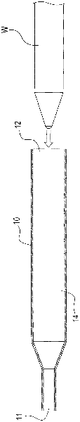
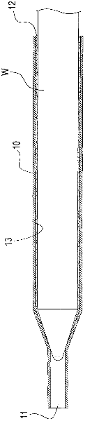
[0076] Please refer to Figure 1 to Figure 10 , which shows the first embodiment of the present invention. The present invention provides a through-type heat pipe structure 1 and a manufacturing method thereof. The fabrication method of the through-type heat pipe structure 1 of the present invention will be described below according to the accompanying drawings, so as to help understand the composition of the through-type heat pipe structure 1 of the present invention.

[0077] The manufacturing method of the threaded heat pipe structure of the present invention, its steps comprise as follows:

[0078] a) providing a first pipe body, the two ends of the first pipe body are respectively formed with a first degassing port and ...


PUM


Abstract

The invention discloses a cross-under type heat pipe structure and a manufacturing method of the cross-under type heat pipe structure. The cross-under type heat pipe comprises a first heat pipe and a second heat pipe, wherein the first heat pipe comprises a first pipe body, a first capillary organization and a first operating fluid, wherein the first pipe body is provided with a hollow containing cavity and an opening; the first capillary organization is arranged on the wall surface of the hollow containing cavity, and the first operating fluid is filled in the hollow containing cavity; the second heat pipe penetrates into the first pipe body from the opening, one part of region of the second heat pipe is contained and sealed in the hollow containing cavity, and a gas channel is formed between the outer wall of the second heat pipe and the inner wall of the first pipe body; and the cross-under type heat pipe structure formed by the first heat pipe and the second heat pipe through cross under is suitable for long-range heat conduction, and the heat conduction efficiency is improved.

Description

technical field [0001] The invention relates to a heat pipe structure, in particular to a threaded heat pipe structure and a manufacturing method thereof. Background technique [0002] The structure of the heat pipe mainly includes: a closed tube body, a capillary tissue arranged on the inner wall of the tube body, and a working fluid filled inside the tube body; when in use, the end of the heat pipe contacting the heat source is called the endothermic section (evaporating end), and the other end is called exothermic section (condensing end); when in use, the heat of the heat source is absorbed by the working fluid in the endothermic section, causing the working fluid in the endothermic section to change from the liquid state after absorbing heat. In gaseous state, the gaseous working fluid flows to the exothermic section due to the temperature difference in the heat pipe, and then releases heat in the exothermic section to return to a liquid state, and the liquid working fl...

Claims


Application Information

Patent Timeline
Patent Type & Authority Applications(China)
IPC IPC(8): F28D15/04
Inventor 黄昱博
Owner KUNSHAN JUZHONG ELECTRONICS
Why Eureka
Try Eureka