
Intelligent photoelectric magnetic flow meter

An opto-electromagnetic and flowmeter technology, applied in the application of electromagnetic flowmeters to detect fluid flow, volume/mass flow generated by electromagnetic effects, etc., can solve problems such as restricting accuracy, inability to satisfy users, and low accuracy, and improve measurement accuracy. , considerable market prospects, the effect of improving the degree of precision

Inactive Publication Date: 2014-02-19
SHENYANG BEIXING INSTR MFG CO LTD +1
View PDF6 Cites 0 Cited by
  • Summary
  • Abstract
  • Description
  • Claims
  • Application Information

AI Technical Summary

Problems solved by technology

Especially in the field of flow measurement, the structure of the metal rotameter restricts the improvement of its accuracy, and the metal rotameter has no remote transmission function, which cannot meet the needs of users and restricts the development of the instrument.
Although the electromagnetic flowmeter has the function of remote transmission, the accuracy is also higher than that of the metal flowmeter, but the instrument requires electrical conductivity for the medium and cannot measure gas, which also restricts the use and development of the instrument.
In addition, orifice flowmeters, V-cone flowmeters, target flowmeters, rotameters, float flowmeters, electromagnetic flowmeters, ultrasonic flowmeters, laser flowmeters, etc. are common technical problems with low precision.

Method used


Image

  • Intelligent photoelectric magnetic flow meter
  • Intelligent photoelectric magnetic flow meter
  • Intelligent photoelectric magnetic flow meter

Examples


Embodiment Construction

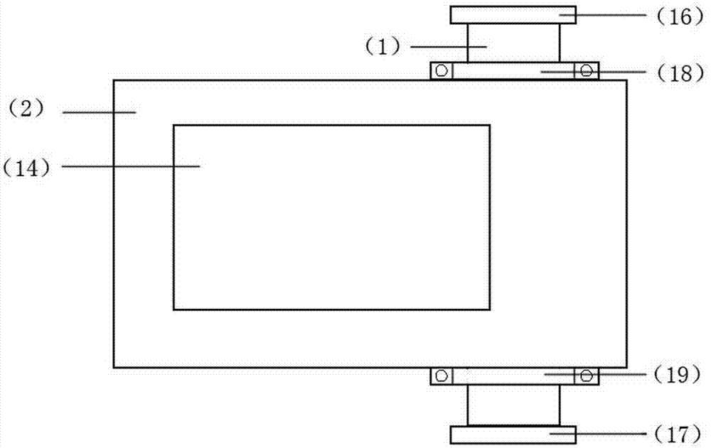
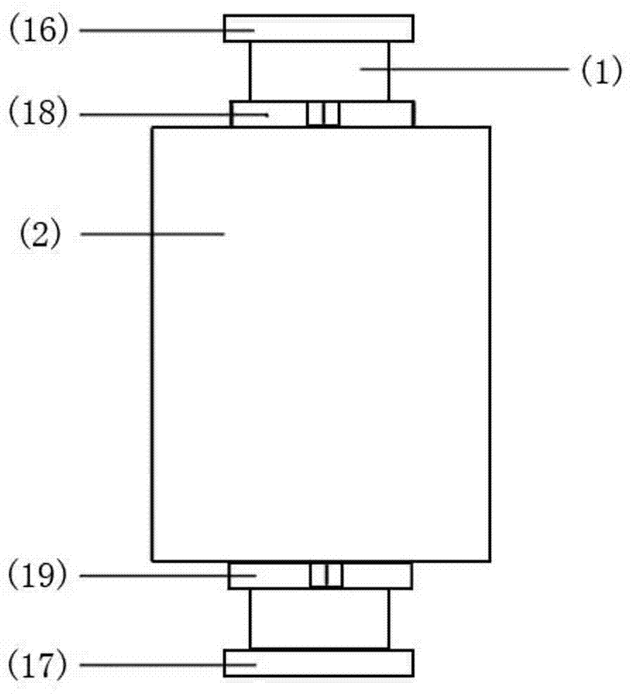
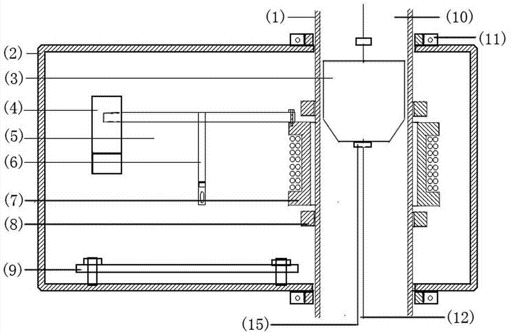
[0027] Such as Figure 1 to Figure 4 As shown, the present invention is an intelligent optical electromagnetic flowmeter, which adopts a closed-loop control system. The pipe 1 to be measured is penetrated through the casing 2. The central shaft 12 in the pipe 1 to be measured is covered with a magnetic rotor 3, and both ends of the magnetic rotor 3 are provided with magnetic rotor limits 15; A magnetic induction coil 7 with a skeleton is provided on the outside of the pipeline 1 to be measured. The skeleton of the magnetic induction coil 7 is connected to one end of the linkage device 5, and the linkage device 5 is fixed in the housing 2 through a bracket 6; the measuring magnetic induction coil 7 The outer diameter is larger than the outer diameter of the pipe 1 to be measured, and the number of turns of the magnetic induction coil 7 corresponds to the magnetic field strength of the magnetic rotor 3. The rear end of the linkage device 5 is connected to the magnetic induction ...


PUM


Abstract

The invention belongs to the technical field of metering and measurement of instruments and apparatuses and particularly relates to an intelligent photoelectric magnetic flow meter which is the electromagnetic and photoelectric combined flow meter realizing the high-precision intelligent processing by using a microprocessor. According to the intelligent photoelectric magnetic flow meter, a measured pipeline penetrates through a housing, a magnetic rotor is sleeved on a central shaft in the measured pipeline, and restrainers of the magnetic rotor are arranged at the two ends of the magnetic rotor; a magnetic induction coil with a backbone is arranged outside the measured pipeline in the housing and is connected with the rear end of a linkage device, and the linkage device is fixed inside the housing through a bracket; light emitting and receiving devices are arranged at the two sides at the front end of the linkage device, and a microprocessor system and a display panel are arranged inside the housing; the housing is provided with a display window; and flange plates are respectively arranged at the upper part and the lower part of the measured pipeline. The intelligent photoelectric magnetic flow meter is obvious in measurement accuracy and relatively high in follow-up ability, is capable of measuring gas, liquid, acidic and alkali media and media with different densities and viscosities and has wide application field, considerable market prospect and practical value.

Description

Technical field [0001] The invention belongs to the technical field of instrumentation measurement and measurement, and in particular relates to an intelligent optical electromagnetic flowmeter, which realizes high-precision intelligent processing through a combination of electromagnetic and photoelectric using a microprocessor. Background technique [0002] In the era of rapid development of science and technology, the demand for intelligent instruments has become more and more obvious and gradually replaced older instruments with lower precision. Especially in the field of flow measurement, the structure of the metal rotor flowmeter restricts the improvement of its accuracy, and the metal rotor flowmeter has no remote transmission function that cannot meet the needs of users and restricts the development of the instrument. Although the electromagnetic flowmeter has the remote transmission function, the accuracy is also higher than that of the metal flowmeter, but the meter requ...

Claims


Application Information

Patent Timeline
Patent Type & Authority Patents(China)
IPC IPC(8): G01F1/58
Inventor 陈明杰赵绪财陈平
Owner SHENYANG BEIXING INSTR MFG CO LTD
Learn More