
Electric control locking pin for electric automobile charging pipe

A technology for electric vehicles and charging piles, which is applied to circuits, electrical components, parts of connecting devices, etc., can solve the problems of low safety, high power consumption, and the inability of electromagnetic locks to inspect the working state, so as to facilitate mechanical unlocking. , to ensure the effect of reliability

Inactive Publication Date: 2014-11-05
江苏洋洋电气科技有限公司 +1
View PDF4 Cites 0 Cited by
  • Summary
  • Abstract
  • Description
  • Claims
  • Application Information

AI Technical Summary

Problems solved by technology

[0003] At present, the charging piles of electric vehicle charging piles basically use mechanical locks to lock the charging guns, which are not very safe. Although some charging piles are equipped with electromagnetic locks, the electromagnetic locks cannot inspect their working status, and most of them use electromagnets to attract and lock them. The power source needs to be continuously powered to maintain an unnatural state. In the actual use process, there is a lot of power consumption, which does not meet the current low-energy and environmental protection requirements.

Method used


Image

  • Electric control locking pin for electric automobile charging pipe
  • Electric control locking pin for electric automobile charging pipe
  • Electric control locking pin for electric automobile charging pipe

Examples


Embodiment Construction

[0022] In order to further explain the technical means and effects of the present invention to achieve the intended purpose of the invention, the specific implementation methods of the present invention are described in detail below in conjunction with the accompanying drawings and preferred embodiments.

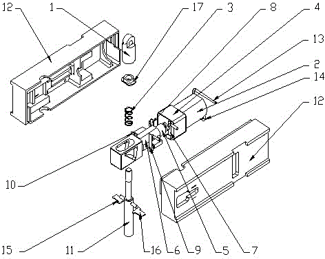
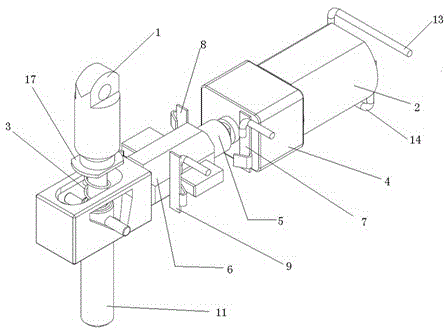
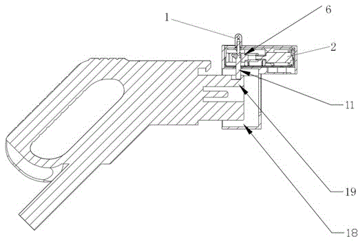
[0023] figure 1 It is a schematic diagram of an embodiment of the technical solution of the present invention, such as figure 1 As shown, an electronically controlled locking pin of an electric vehicle charging pile includes a horizontal movable locking pin 11 arranged in a casing 12, a return spring 3, a copper slider 6, a screw rod 5, a DC motor 2, and a DC motor 2 One end of the screw rod 5 is connected, and the other end of the screw rod 5 is connected to the copper slider 6. The copper slider 6 is in movable contact with the horizontal movable lock pin 11, and the contact position is matched with a steering mechanism. The axes are perpendicular to each other; the horiz...


PUM


Abstract

The invention relates to an electric control locking pin for an electric automobile charging pipe. The electric control locking pin comprises a horizontal type movable locking pin 11 arranged in a shell 12, a resetting spring 3, a copper sliding block 6, a screw rod 5 and a direct-current motor 2; the direct-current motor 2 is connected with one end of the screw rod 5; the other end of the screw rod 5 is connected with the copper sliding block 6; the copper sliding block 6 and the horizontal type movable locking pin 11 are in movable contact; a steering mechanism is arranged on a contact position in a matching way; the axial direction of the screw rod 5 is vertical to the axial direction of the horizontal type movable locking pin 11; the resetting spring 3 is further sleeved on the horizontal type movable locking pin 11; one end of the resetting spring 3 is positioned on the shell 12 through a limiting gasket 17; and position signal devices are arranged at both ends of the copper sliding block 6 and a position which the horizontal type movable locking pin 11 is located. The electric control locking pin provided by the invention can conveniently observe a working state of a motor locking pin by arranging the position signal devices. The energy consumption of an electric piece can be well reduced through the electric energy allocation. The electric control locking pin provided by the invention is convenient for a user to mechanically unlock due to designs of a pull ring and the resetting spring, so that the system reliability is ensured.

Description

technical field [0001] The invention relates to a component of an electric vehicle charging pile, in particular to an electronically controlled lock pin of a socket in the electric vehicle charging pile. Background technique [0002] The invention relates to a component of an electric vehicle charging pile, in particular to an electronically controlled lock pin of a socket in an electric vehicle charging pile [0003] At present, the charging piles of electric vehicle charging piles basically use mechanical locks to lock the charging guns, which are not very safe. Although some charging piles are equipped with electromagnetic locks, the electromagnetic locks cannot inspect their working status, and most of them use electromagnets to attract and lock them. The power source needs to be continuously powered to maintain an unnatural state. In the actual use process, there is a lot of power consumption, which does not meet the current low-energy and environmental protection requi...

Claims


Application Information

Patent Timeline
Patent Type & Authority Patents(China)
IPC IPC(8): H01R13/639
Inventor 赵红如
Owner 江苏洋洋电气科技有限公司
Learn More