Driving apparatus of sensorless brushless motor

A technology for brushless motors and drive equipment, applied in the direction of AC motor control, electronic commutation motor control, single motor speed/torque control, etc., can solve the problems of complex circuit design, high cost, and low cost

Inactive Publication Date: 2012-08-15
AISIN SEIKI KK
View PDF6 Cites 4 Cited by
  • Summary
  • Abstract
  • Description
  • Claims
  • Application Information

AI Technical Summary

Problems solved by technology

The design of a circuit that provides an automatic and continuously changing PWM frequency is complex
As a result, the speed control device disclosed in JPH8-23694A necessarily has a high cost and is not suitable for providing a low-cost sensorless brushless motor driving device

Method used


Image

  • Driving apparatus of sensorless brushless motor
  • Driving apparatus of sensorless brushless motor
  • Driving apparatus of sensorless brushless motor

Examples


Embodiment Construction

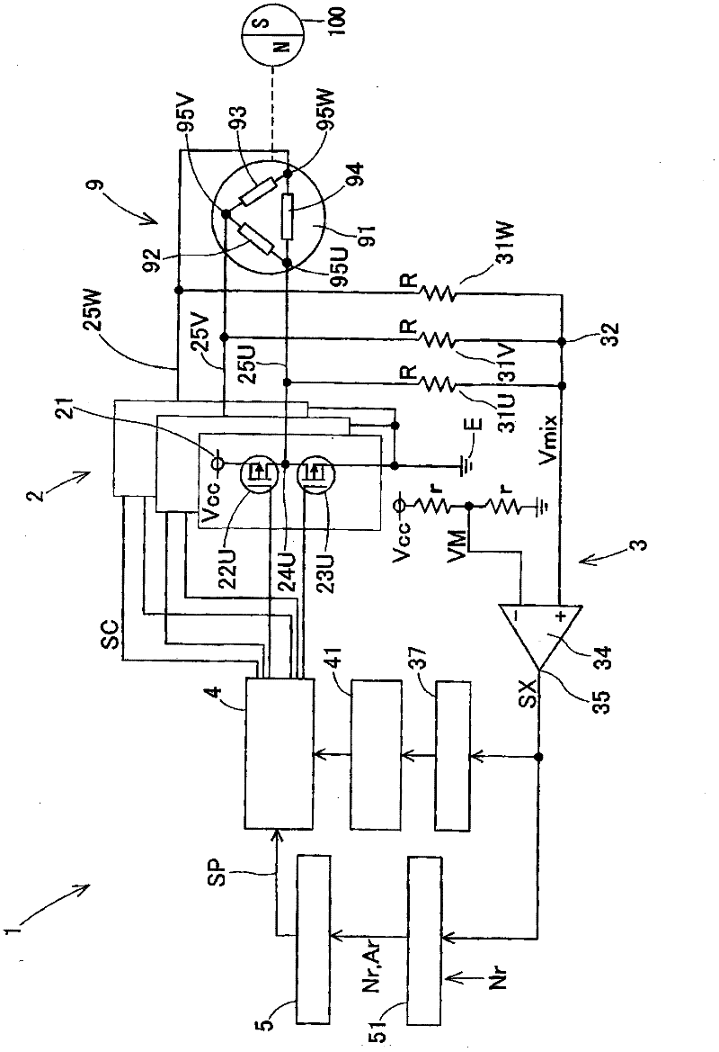
[0043] For the purpose of describing an embodiment of the sensorless brushless motor 9 driving device 1 according to the present invention, the length of time during which the power supply voltage Vcc is supplied within one PWM frequency cycle is referred to as an operation period. The length of time for which the power supply voltage Vcc is continuously supplied to a predetermined phase with a plurality of operation periods higher than or close to 120 electrical degrees is referred to as a power-on time zone. Generally speaking, the working period is much shorter than the power-on time zone.

[0044] will refer to figure 1 The configuration and driving operation of the driving device 1 of the sensorless brushless motor 9 according to the first embodiment are described to FIG. 5 . Configure as figure 1 The drive device 1 shown powers up a sensorless brushless motor 9 by using an inverter circuit 2 in which the duty ratio of a power supply voltage is changed by a PWM (Pulse W...


PUM


Abstract

A driving apparatus (1, 10, 11) of a sensorless brushless motor (9, 90) includes an inverter circuit (2) supplying a power supply voltage (Vcc), of which duty ratios (A) is variably controlled by a pulse-width modulation method, a PWM generator circuit (5, 50) generating a pulse-width modulation signal (SP), a position detection circuit (3, 30) operating at a predetermined phase of the pulse-width modulation signal (SP) and detecting a rotational position of the rotor (100), and an inverter control circuit (4) transmitting an energization control signal (SC) determined based on the pulse-width modulation signal (SP) to the inverter circuit (2). The PWM generator circuit (5, 50) provides a stepwise increase and decrease of a pulse-width modulation frequency in a normal PWM frequency (fN), a low-speed PWM frequency (fL), and a high-speed PWM frequency (fH) in response to an increase and decrease of one of following parameters; the commanded duty ratio (Ar), the commanded number of rotations of the motor (Nr), a detected duty ratio (Am), and a detected number of rotations of the motor (Nm).

Description

technical field [0001] The present disclosure generally relates to a drive device for a sensorless brushless motor. Background technique [0002] As one type of DC brushless motor, a sensorless type motor (not provided with a sensor for detecting the rotational position of a rotor for cost reduction reasons) is known and put into practical use. A known sensorless brushless motor is provided with a position detection circuit for detecting the rotational position of a rotor with respect to a pair of magnetic poles of the rotor by detecting an induced voltage generated at one end of an armature winding of a stator of the motor . Based on the detected rotational position of the rotor, the power supply control device determines an energization time zone for supplying the power supply voltage to the armature winding. A power supply circuit (which is generally configured by an inverter circuit) supplies a power supply voltage to the armature winding according to the determined po...

Claims


Application Information

Patent Timeline
Patent Type & Authority Applications(China)
IPC IPC(8): H02P6/08H02P6/18H02P6/06H02P6/182
CPCH02P27/085H02P6/182H02P6/28H02P6/153
Inventor 音川昌也济木浩一永畑幸真
Owner AISIN SEIKI KK
Why Eureka
Try Eureka