Mitigating potential for urea deposit formation in engine exhaust

An engine, internal combustion engine technology, applied in the direction of engine components, combustion engines, machines/engines, etc., can solve problems such as initial time delay

Inactive Publication Date: 2012-08-15
INT ENGINE INTPROP CO LLC
View PDF6 Cites 7 Cited by
  • Summary
  • Abstract
  • Description
  • Claims
  • Application Information

AI Technical Summary

Problems solved by technology

However, this delays the initial time for the exhaust gas to be treated by SCR

Method used


Image

  • Mitigating potential for urea deposit formation in engine exhaust
  • Mitigating potential for urea deposit formation in engine exhaust
  • Mitigating potential for urea deposit formation in engine exhaust

Examples


Embodiment Construction

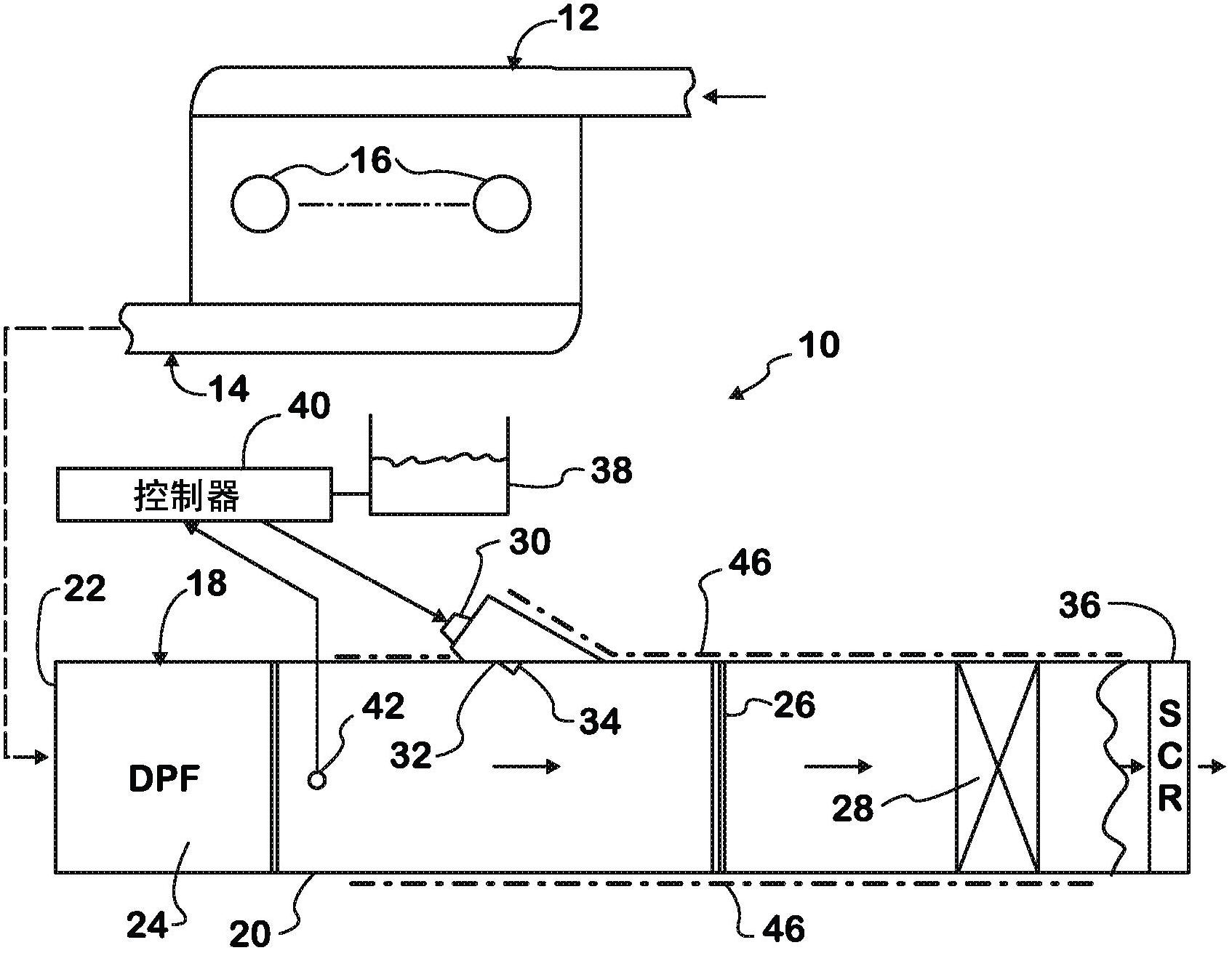
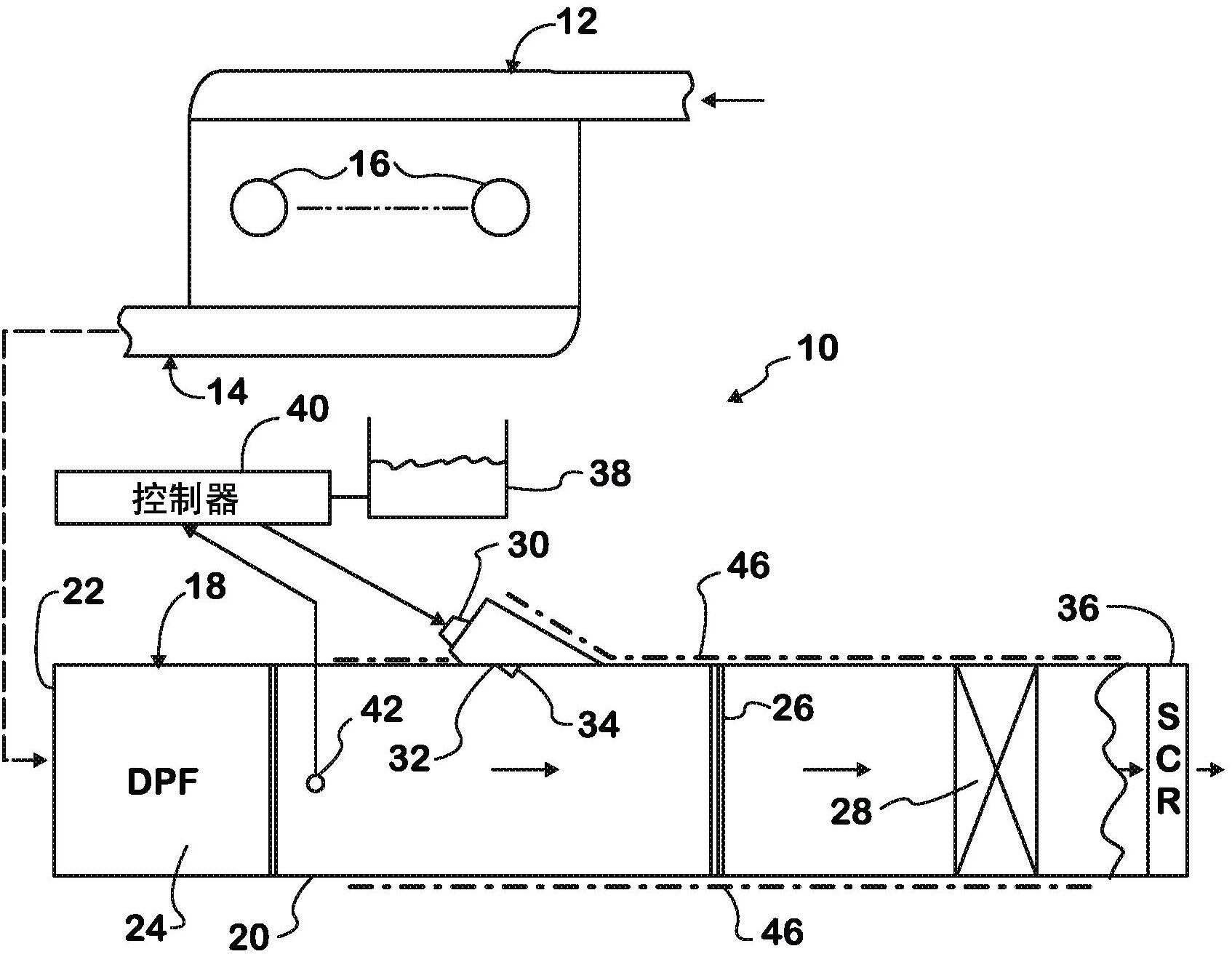
[0018] figure 1 An example of a turbocharged diesel engine 10 is shown having an intake system 12 through which charge air enters and an exhaust system 14 through which exhaust gases from combustion exit. All the details that these two systems usually have. Engine 10 includes a plurality of cylinders 16 forming combustion chambers into which fuel is injected by fuel injectors for combustion with charge air admitted through an intake system 12 . The energy generated by combustion powers the engine via pistons connected to the crankshaft.

[0019] When used in a motor vehicle, such as a truck, engine 10 is coupled through a driveline to driven wheels that propel the vehicle. The intake valves control the admission of charge air into the cylinders 16 and the exhaust valves control the flow of exhaust gases out through the exhaust system 14 and eventually into the atmosphere. Before entering the atmosphere, however, the exhaust is treated by one or more aftertreatment devices i...


PUM


Abstract

A device and method for catalytic reduction of NOx in gaseous products of a combustion process before entry into the atmosphere. The gaseous and particulate products of a combustion process flow radially through a radial flow particulate filter element (24) that is effective to trap particulate matter, and are then directed axially through a collector (26). An injector (30) introduces a reductant into an axial end of the collector for entrainment with axial flow through the collector in a direction away from the injector. Flow leaving the collector is directed through an SCR catalyst (40) where catalytic reduction of NOx occurs.

Description

technical field [0001] The present invention relates to internal combustion engines, in particular diesel engines similar to those used to propel large trucks, and in particular the present invention relates to engine exhaust aftertreatment comprising spraying a urea solution into the engine exhaust system, Used to promote the selective catalytic reduction (SCR) of certain components of engine exhaust. Background technique [0002] One example of a diesel exhaust aftertreatment system using selective catalytic reduction (SCR) includes injectors through which an aqueous urea solution is injected into the exhaust gas stream. Ideally, the solution should be completely vaporized and thoroughly mixed with the exhaust gas before the exhaust stream flows over the catalytic surface. [0003] The geometry of the exhaust aftertreatment system and the spray pattern of the urea injectors may cause some of the injected solution to wet the interior surfaces of the exhaust system prior to...

Claims


Application Information

Patent Timeline
Patent Type & Authority Applications(China)
IPC IPC(8): F01N3/00
CPCF01N3/2013F01N3/2066F01N2240/20F01N2250/02F01N2560/06F01N2570/14F01N2610/02Y02A50/20Y02T10/12
Inventor B·J·阿德尔曼V·O·斯特罗兹S·桑莎纳姆E·M·德雷保斯基
Owner INT ENGINE INTPROP CO LLC
Why Eureka
Try Eureka