Low-head Kaplan turbine regulating method

A water turbine and paddle-turning technology, which is applied to hydroelectric power generation, mechanical equipment, engine components, etc., can solve the problems of unit flow reduction, unit stability reduction, guide vane opening reduction, etc., to increase braking torque, Improved stability and simple structure

Active Publication Date: 2012-08-22
POWERCHINA XIBEI ENG
View PDF4 Cites 2 Cited by
  • Summary
  • Abstract
  • Description
  • Claims
  • Application Information

AI Technical Summary

Problems solved by technology

This adjustment is well known, but there are two problems. It is correct to improve the efficiency of the turbine and obtain the maximum energy during normal operation and start-up. However, it is correct when the turbine is shut down or transitioned from power generation to phase modulation. The hydraulic turbine has a transition period from the working condition of the turbine to the working condition of the reverse pump and the phase modulation and compression. At this time, this adjustment: 1. During the period of shutdown or transition from power generation to phase modulation (phase modulation and compression), the turbine has In the working condition of the reverse water pump, in this case, the decrease of the opening of the guide vane, the decrease of the flow rate of the unit, and the decrease of the angle of the runner blades are the increase of the head of the reverse water pump, which becomes the cause of the shutdown of the vertical unit and the lifting of the machine during the transition process. The main factors, such as Gezhou unit shut down and lift up, and the Syrian Dishlin power station unit designed by our institute is lifted during the process of phase modulation and compression, etc., increase the axial rear thrust of the horizontal unit, which reduces the stability of the unit
2. At this time, the unit does not need to obtain a lot of water energy and needs to stop quickly or the transition process is completed quickly. According to the above adjustment, the movable guide vanes of the water turbine are all closed to 0 opening, and the runner blades will be reduced to the minimum angle position. Small, can make the turbine get the maximum water energy in the process, which is not conducive to the reduction of shutdown and transition time

Method used


Image

  • Low-head Kaplan turbine regulating method
  • Low-head Kaplan turbine regulating method
  • Low-head Kaplan turbine regulating method

Examples


Embodiment Construction

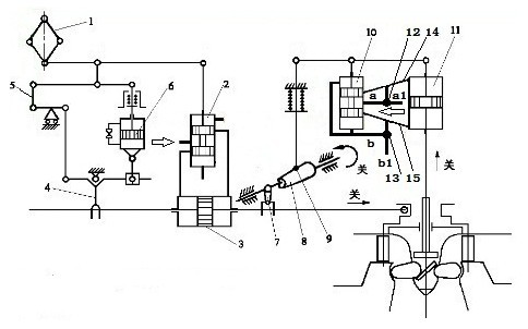
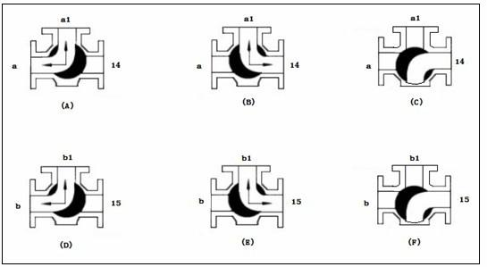
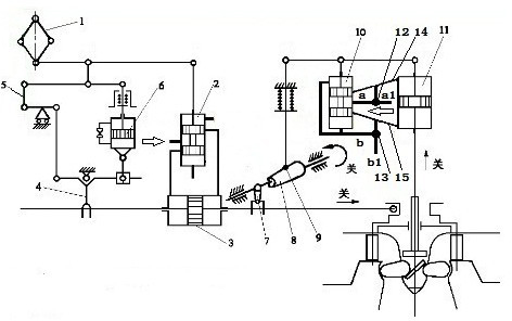
[0017] like figure 1 As shown, the first three-way valve 12 is connected to the oil supply passage a1, and the second three-way valve 13 is connected to the oil return passage b1.

[0018] The oil supply pipe a of the vane pressure distribution valve 10 is connected to the first port of the first three-way valve 12, the oil supply circuit a1 is connected to the second port of the first three-way valve 12, and the first oil pipe 14 is connected to the first three-way valve 12 the third pass.

[0019] The oil return pipe b of the vane pressure distribution valve 10 is connected to the first port of the second three-way valve 13, the oil return line b2 is connected to the second port of the second three-way valve 13, and the second oil pipe 15 is connected to the first port of the second three-way valve 13. tee.

[0020] Under normal starting and running conditions, the oil supply pipe a and the oil supply oil passage a1 are connected through the first three-way valve 12, and ...


PUM


Abstract

The invention relates to a low-head Kaplan turbine regulating method, which is characterized by, under the normally-on and operating condition of a turbine, enabling the communication between an oil supply pipe a and an oil supply path a1 via a first three-way valve (12) while disabling the communication between a first oil pipe (14) and the oil supply pipe a and the oil supply path a1; and enabling the communication between an oil return pipe b and an oil return path b1 via a second three-way valve (13) while disabling the communication between a second oil pipe (15) and the oil return pipe b and the oil return path b1. The first three-way valve (12) is connected on the oil supply path a1, and the second three-way valve (13) is connected on the oil return path b1. According to the inventive method, a turbine can obtain stable performance under shutdown condition or in the process of transiting from a power generation working condition to a phase regulation working condition, to reduce shutdown and transition time.

Description

technical field [0001] The invention belongs to hydraulic mechanical engineering, in particular to a method for adjusting a low-head swirling water turbine. Background technique [0002] The regulation system of the low-head rotary paddle turbine is double regulation, that is, the movable guide vane of the turbine is linked with the runner blade. It has been proved by experiments and practice that the low-head turbine adopts double regulation, which can enable the turbine to obtain a wider high-efficiency area, improve the overall efficiency of the turbine, maximize the use of water energy, and obtain the maximum kinetic energy. The double adjustment is adjusted in this way: with the increase of the output of the unit, the opening of the movable guide vane increases, the application flow of the turbine increases, the angle of the runner blade increases, and the output of the unit decreases; vice versa; when the unit stops, the opening of the movable guide vane decreases. Sm...

Claims


Application Information

Patent Timeline
Patent Type & Authority Applications(China)
IPC IPC(8): F03B15/12
CPCY02E10/20
Inventor 王耀洲
Owner POWERCHINA XIBEI ENG
Why Eureka
Try Eureka