Capacity control type rotary compressor
A rotary compressor and capacity control technology, applied in the field of rotary compressors, can solve problems such as compressor failure, insufficient heating capacity, insufficient refrigeration capacity, etc., and achieve the effects of solving the problem of overheating, simple and reasonable structure, and low production cost
- Summary
- Abstract
- Description
- Claims
- Application Information
AI Technical Summary
Problems solved by technology
Method used
Image

Examples
Embodiment 1
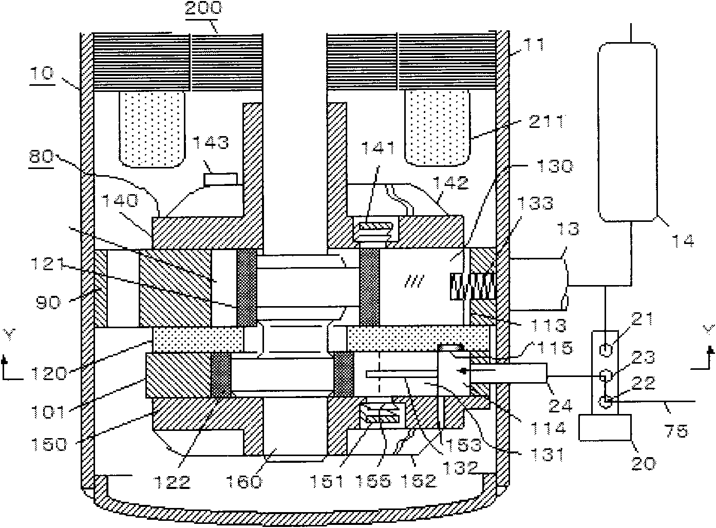
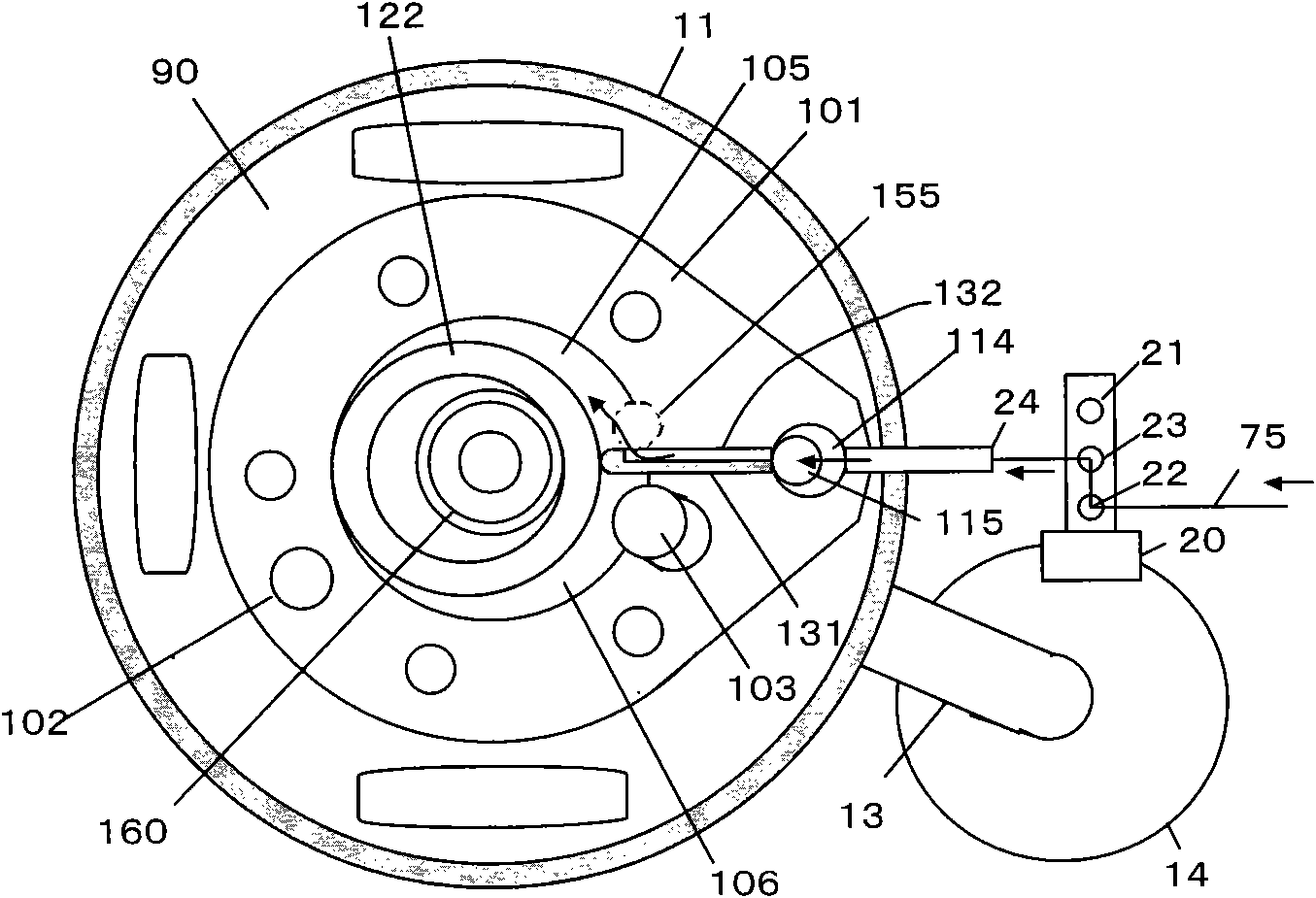
[0027] see figure 1 and figure 2 , is an internal configuration diagram of the capacity control type rotary compressor 10 of the present invention. figure 2 yes figure 1 The Y-Y section diagram in .
[0028] The rotary compressor 10 is composed of a capacity control type compression mechanism 80 installed in the airtight casing 11 and an electric motor 200 arranged on the top of the compression mechanism 80 . The compression mechanism 80 has two cylinders: a first cylinder 90 and a second cylinder 101, the first cylinder 90 and the second cylinder 101 are separated by a middle partition 120, and the central part of each cylinder is respectively divided into a first compression chamber and a second chamber. compression chamber.
[0029] When the total displacement of the first cylinder 90 and the second cylinder 101 of the capacity-controlled compression mechanism 80 is 100, the ratios of the displacements are 65 and 35, respectively. When the first cylinder and the seco...
Embodiment 2
[0070] In Embodiment 1, since the second sliding vane cavity 114 is sealed to become the passage of the liquid refrigerant, there is a possibility that the second sliding vane 131 may wear progressively due to insufficient lubrication. This second embodiment provides a solution to such a problem.
[0071] exist figure 1 and Figure 4 The oil hole 153 shown in , penetrates the cylinder mounting flat portion of the sub-bearing 150 . The lower end of the oil hole 153 opens a hole in the refrigerating machine oil (not shown) accumulated in the bottom of the airtight casing 11 , and the upper end of the oil hole 153 opens a hole in the second vane cavity 114 .
[0072] The opening position of the upper end of the oil hole 153 coincides with the lower moving surface of the second sliding vane 131 , and when the second sliding vane 131 approaches the top dead center, the oil hole 153 opens in the second sliding vane cavity 114 . However, when the second sliding piece 131 moves fro...
Embodiment 3
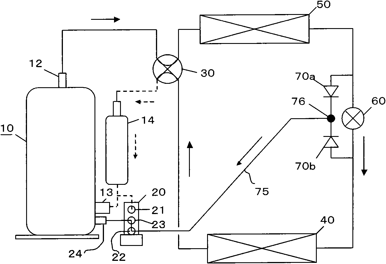
[0078] In the heating cycle and the refrigeration cycle, when it is necessary to change the amount of liquid refrigerant injected into the second cylinder 101, such as Figure 7 As shown, a capillary 71 can be added between the second one-way valve 70b and the first connection point 76 to reduce the injection amount of liquid refrigerant in one of the two cycles. Thus, in Figure 7 When the refrigeration cycle is carried out in the middle, the injection amount of liquid refrigerant is relatively small in the heating cycle.
[0079] See embodiment 2 for all the other undescribed parts, and will not repeat.
PUM
 Abstract
Description
Claims
Application Information
 - R&D
- Intellectual Property
- Life Sciences
- Materials
- Tech Scout
- Unparalleled Data Quality
- Higher Quality Content
- 60% Fewer Hallucinations
Browse by: Latest US Patents, China's latest patents, Technical Efficacy Thesaurus, Application Domain, Technology Topic, Popular Technical Reports.
© 2025 PatSnap. All rights reserved.Legal|Privacy policy|Modern Slavery Act Transparency Statement|Sitemap|About US| Contact US: help@patsnap.com