Lubricating grease filling machine for building machinery

A construction machinery and lubricating grease technology, which is applied in the direction of engine lubrication, lubricating pumps, mechanical equipment, etc., can solve problems such as discontinuous oiling action, manual operation accidents, high risk, etc., to achieve easy and safe lubrication maintenance, stable and reliable work , the effect of high degree of automation

Inactive Publication Date: 2012-08-22
李历强
View PDF0 Cites 5 Cited by
  • Summary
  • Abstract
  • Description
  • Claims
  • Application Information

AI Technical Summary

Problems solved by technology

[0004] 1. The grease gun uses the action of the lever and the spring to squeeze out the butter. It can only squeeze the butter once by breaking the handle once. The oiling action is not continuous. If the amount of grease is large, it will be time-consuming, laborious and inefficient.
[0005] 2. Since the lubricating points on the machine are scattered, people need to climb to various parts of the machine or even the dirty bottom to refill each lubricating point every time they refill. The operation is cumbersome, labor-intensive, and the working environment is poor. , poor security
[0006] 3. Adding butter to a machine that cannot be stopped during operation is extremely dangerous and can easily cause manual work accidents
[0007] 4. Large human factors and high cost of use

Method used


Image

  • Lubricating grease filling machine for building machinery
  • Lubricating grease filling machine for building machinery
  • Lubricating grease filling machine for building machinery

Examples


Embodiment Construction

[0022] The present invention will be further described in conjunction with the accompanying drawings and specific embodiments.

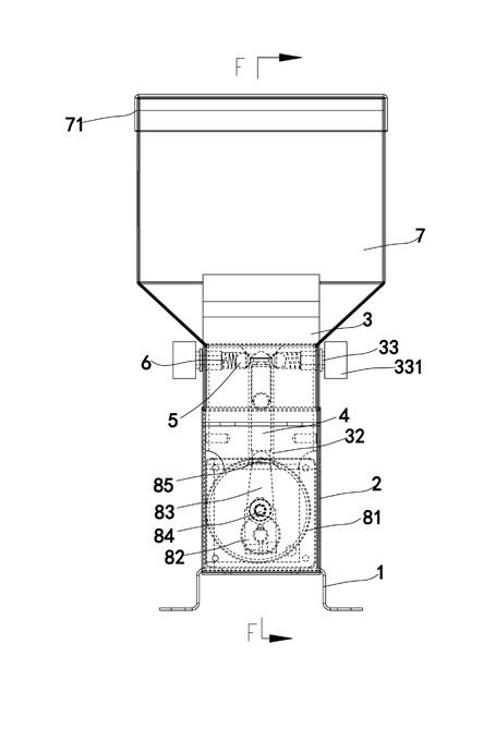
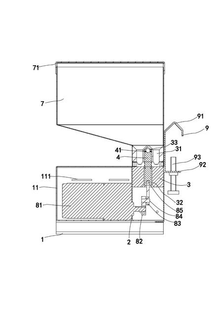
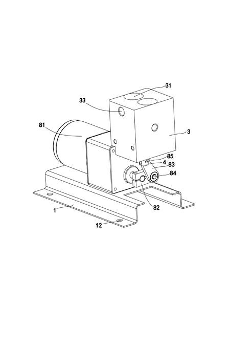
[0023] refer to Figure 1 to Figure 3 , this embodiment discloses a grease filling machine for construction machinery, including a base 1, an oil block bracket 2, an oil block 3, a piston valve core 4, two pressing balls 5, two springs 6 and an oil storage bucket 7 , the oil block bracket 2 is set on the base 1, the oil block 3 is detachably fixed on the top of the oil block support 2 by bolts, and the upper part of the oil block 3 is provided with two oil inlet holes 31 , the lower part is provided with an air pressurization chamber 32, the two oil inlet holes 31 are connected with the air pressurization chamber 32, and the two oil inlet holes 31 on the upper part of the oil block 3 are provided with an air pressurization chamber 32. The two oil outlet holes 33 are connected, and the piston spool 4 is set on the air pressurization chamber 32 of the...


PUM


Abstract

The invention relates to a device for filling lubricating grease into a mechanical system, and provides a lubricating grease filling machine for multi-station building machinery, which has a simple structure and high automation degree, improves the injection efficiency, reduces the injection cost and can easily and safely completes the lubrication maintenance work of each part of a machine. The lubricating grease filling machine comprises a base, a manifold block support, a manifold block, a piston-type valve core, a compression ball, a spring and an oil storage hopper, wherein the manifold block support is arranged on the base, the manifold block is detachably fixed on the manifold block support, the manifold block is provided with an oil inlet hole, an oil outlet hole and an air pressurizing chamber, the oil inlet hole is communicated with the air pressurizing chamber, the air pressurizing chamber is communicated with the oil outlet hole, the piston-type valve core is driven by a drive device to move vertically and is arranged on the air pressurizing chamber of the manifold block, the compression ball is arranged between the air pressurizing chamber and the oil outlet hole, the spring is arranged inside the oil outlet hole, one end of the spring is pushed against the ball, the other end of the spring is pushed against a spring arrangement boss, and the oil storage hopper is arranged on the manifold block support and above the oil inlet hole of the manifold block.

Description

[0001] technical field [0002] The invention relates to a device for adding lubricating grease to a mechanical system, in particular to a construction machinery lubricating grease filling machine. Background technique [0003] Existing construction machinery generally adopts manual lubrication for the lubrication of grease, and directly smears the lubrication parts required by the construction machinery through a brush or manually fills the grease into the grease gun, and then lifts the grease gun to add oil to each lubrication point one by one. Note lubricating butter, the main disadvantages of manual lubrication are: [0004] 1. The grease gun uses the action of the lever and the spring to squeeze out the butter. It can only squeeze the butter once by breaking the handle once. [0005] 2. Since the lubricating points on the machine are scattered, people need to climb to various parts of the machine or even the dirty bottom to refill each lubricating point every time they...

Claims


Application Information

Patent Timeline
Patent Type & Authority Applications(China)
IPC IPC(8): F16N11/08F16N13/06F16N13/10F16N21/00F16N19/00
Inventor 李历强
Owner 李历强
Why Eureka
Try Eureka