Transmission line malfunction positioning method based on non-contact magnetic measurement

A magnetic field measurement, transmission line technology, applied in the direction of the fault location, etc., can solve problems such as a lot of time, and achieve the effect of high sensitivity, low cost, and high bandwidth

Inactive Publication Date: 2012-08-22
UNIV OF ELECTRONIC SCI & TECH OF CHINA +1
View PDF5 Cites 32 Cited by
  • Summary
  • Abstract
  • Description
  • Claims
  • Application Information

AI Technical Summary

Problems solved by technology

For long-distance power transmission, the accuracy of fault location becomes especially important, because even a small algorithm error will lead to a difference of several kilometers in fault location, which makes maintenance personnel spend more time to find the point of failure
Especially in some mountainous areas (such as Liangshan in China), this fault location system may cause an error of ± 3km in the 500KV transmission line, so maintenance personnel have to walk about

Method used


Image

  • Transmission line malfunction positioning method based on non-contact magnetic measurement
  • Transmission line malfunction positioning method based on non-contact magnetic measurement
  • Transmission line malfunction positioning method based on non-contact magnetic measurement

Examples


Embodiment Construction

[0050] The present invention is described in detail below in conjunction with attached figure:

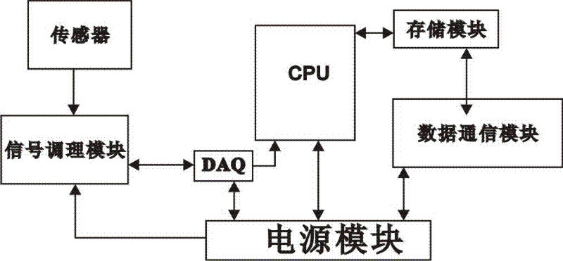
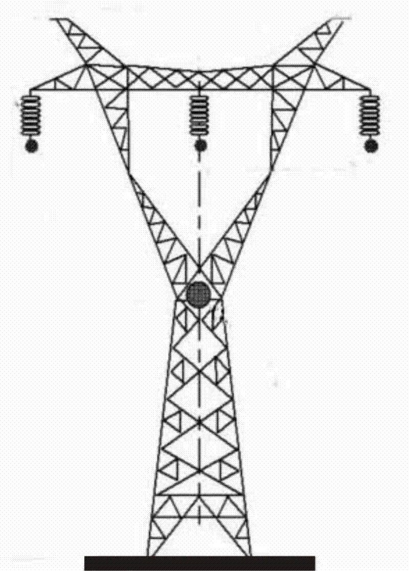
[0051] For the application of fault location, it is enough if the fault location can be determined within a span (such as 400m-1000m) of two adjacent transmission towers. Once the span where the fault occurs is determined, line maintenance personnel can easily find the fault point within the span. In this scenario, we propose to install sensitive sensors on each transmission tower (for long spans, it can be done in the middle of the span or with additional measuring terminals installed). The overall scheme of the solution is as follows Figure 1-2 as shown, figure 2 The circles indicate the location of remote monitoring terminals, i.e. sensors. The data collected from the remote terminal can be displayed graphically in combination with GIS (Geographic Information System) technology in the client software, which is convenient for maintenance personnel to quickly find the fault ...


PUM


Abstract

The invention discloses a transmission line malfunction positioning method based on non-contact magnetic measurement. The method is characterized by comprising step A, confirming a malfunction section; step B, identifying the type of the malfunction; and step C, internally positioning the malfunction section, wherein the malfunction section is confirmed by the following ways: constructing a remote terminal arranged on a transmission steel pylon, wherein the remote terminal consists of a microprocessor CPU (Central Processing Unit), a sensor, a signal regulating module, a data acquisition module DAQ (Data Acquisition), a storing module, a data communication module and a power supply module, wherein the sensor is used for measuring the three-dimensional component of the magnetic field at a three-dimensional space, and the data is transmitted to the DAQ module after passing through the signal regulating module. The invention provides a new transmission line malfunction positioning method based on the non-contact magnetic measurement. The malfunction section is positioned according to the magnetic data near the transmission line measured by a magneto-resistance magnetic field sensor with high sensibility, high band width and low cost.

Description

technical field [0001] The invention relates to a transmission line fault location, in particular to a transmission line fault location method based on non-contact magnetic field measurement. Background technique [0002] Overhead transmission lines are widely used for power transmission between the power generation area and the receiving end grid. In recent years, with the rapid development of the power system, there are more and more transmission lines. These lines are prone to failure due to lightning strikes, short circuits, equipment failures, misuse, overload, etc. Statistics show that transmission line faults are the most common faults in power systems. When a transmission line fails, detecting and locating the fault is of great significance for the inspection personnel to maintain the line and restore the system power supply as soon as possible. The time to determine the fault point of the line is an important index for evaluating the power transmission, and there...

Claims


Application Information

Patent Timeline
IPC IPC(8): G01R31/08
Inventor 黄琦甄威丁理杰姚若婷易建波井实张昌华卢有亮
Owner UNIV OF ELECTRONIC SCI & TECH OF CHINA
Why Eureka
Try Eureka