
In vitro bionic cycle test system for simulating flowing of blood in arterial aneurysm of human body

A technology of blood flow and experimental system, applied in the field of biomedical research, can solve the problems of unfavorable mechanism of action, difficulty in understanding and understanding the mechanism of thrombus formation in aneurysm, and inability to achieve rapid and precise adjustment

Inactive Publication Date: 2012-08-22
XI AN JIAOTONG UNIV
View PDF3 Cites 26 Cited by
  • Summary
  • Abstract
  • Description
  • Claims
  • Application Information

AI Technical Summary

Problems solved by technology

[0004] The flow state of human blood has different effects on blood flow velocity, wall shear stress and intratumoral eddy current at different heartbeat frequencies, and the heartbeat frequency cannot be quickly and accurately adjusted in traditional in vitro bionic experimental research.
Therefore, the simulation of the blood flow state at different heartbeat frequencies has caused great limitations, which is not conducive to the study of the mechanism of action between heart rate changes and hemodynamic factors, and to understand the development and evolution of aneurysms and aneurysms. The mechanism of thrombus formation within the

Method used


Image

  • In vitro bionic cycle test system for simulating flowing of blood in arterial aneurysm of human body
  • In vitro bionic cycle test system for simulating flowing of blood in arterial aneurysm of human body
  • In vitro bionic cycle test system for simulating flowing of blood in arterial aneurysm of human body

Examples


Embodiment Construction

[0019] The present invention will be described in further detail below in conjunction with the accompanying drawings.

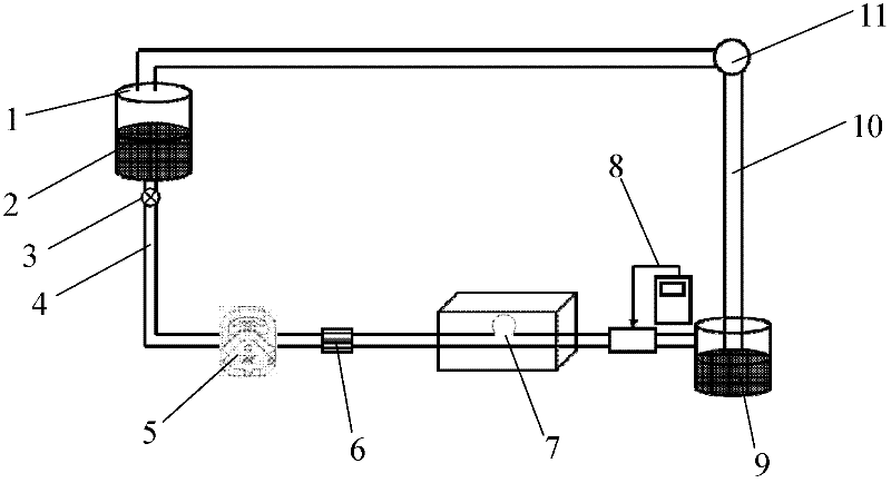
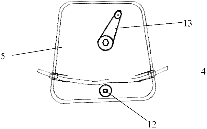
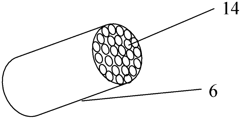
[0020] see figure 1 , the present invention includes the upper and lower liquid storage tanks 1, 9 connected by pipelines and forming a closed circulation loop. The tanks 1 and 9 are provided with a fluid working medium 2, and the outlet of the upper liquid storage tank 1 communicates with the laminar flow generator 6 through a silicone hose 4 with a valve 3, and the silicone hose 4 passes through a peristaltic pump 5, The laminar flow generator 6 is connected to the entrance of the experimental section 7, the flowmeter 8 and the lower liquid storage tank 9 through the rubber tube 10. Since the experimental model is a glass curved surface, in order to avoid the scattering effect of the laser on the curved surface during the measurement process, the experimental section 7 is fixed in the plexiglass cavity, which is filled with fluid working medium, the outlet...


PUM

PropertyMeasurementUnit
Kinematic viscosityaaaaaaaaaa

Abstract

The invention discloses an in vitro bionic cycle test system for simulating flowing of blood in arterial aneurysm of a human body under different heartbeat frequencies, relating to the field of biomedicine research on arterial aneurysm and being suitable for carrying out cycle simulating testing on the flowing condition of the blood in the arterial aneurysm of the human body under different heartbeat frequencies. The in vitro bionic cycle test system comprises an upper liquid storage box, a peristaltic pump, a laminar flow generator, an experimental section model, a flow meter, a lower liquid storage box, a cycle pump and a valve. The whole in vitro bionic cycle test system is communicated by a silicon rubber hose and a common rubber hose, fluid is controlled by the valve to flow or stop flowing; the silicon rubber hose is connected to the upper liquid storage box and is downwards connected with the laminar flow generator through the peristaltic pump, a pump head of the peristaltic pump is used for carrying out peristaltic extrusion on the silicon rubber hose; and the laminar flow generator is formed by banding a thin tube embedded in the common rubber hose. Fluid flows out of the laminar flow generator, enters the experimental section model through the common rubber hose, flows into the lower liquid storage box through the flow meter, and returns to the upper liquid storage box through the cycle pump, so that the whole cycle flowing process is completed.

Description

technical field [0001] The invention relates to the field of biomedical research, in particular to an in vitro bionic circulatory experiment system suitable for circulatory simulation of blood flow in human aneurysms under different heartbeat frequencies. Background technique [0002] The human blood flow in vitro bionic circulation experiment system uses the principle of flow similarity to simulate the real blood flow, so as to obtain information similar to the real blood flow. The in vitro bionic experimental system is low in cost, strong in operability, and the experimental conclusion is close to the real situation, so it is widely used in the field of modern biomedical research. [0003] At present, there are many in vitro bionic experimental circulatory systems at home and abroad that simulate blood flow in the human body at a given heart rate, and typical studies such as literature [1] Zhang X, Yao Z, Zhang Y, et al.Experimental and computational studies on the flow f...

Claims


Application Information

Patent Timeline
IPC IPC(8): G09B23/28
Inventor 王跃社马小奇张玉蓉李迪
Owner XI AN JIAOTONG UNIV
Learn More