
Bypass isolating switch for 1100-kV super-high-voltage serial compensation

An isolating switch and UHV technology, which is applied in the field of bypass isolating switch for 1100KV UHV series compensation, can solve the problems of contact ablation, large impact of opening and closing, shortening the normal working cycle of the isolating switch, etc. Force condition, reduce radial force, increase the effect of normal duty cycle

Active Publication Date: 2012-08-22
STATE GRID CORP OF CHINA +4
View PDF6 Cites 14 Cited by
  • Summary
  • Abstract
  • Description
  • Claims
  • Application Information

AI Technical Summary

Problems solved by technology

When working, the rotation of the insulator can be used to drive the lower conductive tube to rotate around its hinge point with the corresponding insulating support to produce a lateral or upright action. The lower conductive tube drives the upper conductive tube through the rack and pinion mechanism while moving. Stretch or fold, so as to complete the on-off between the dynamic and static contacts; the above-mentioned double-column horizontal telescopic outdoor high-voltage AC disconnector solves the problem of large impact on the opening and closing of the disconnector to a certain extent, but its folding telescopic arm After the upper conductive tube is folded together with the lower conductive tube, it is located on the side of the lower conductive tube away from the other post insulator that is arranged side by side with the post insulator where it is located. Therefore, when the folding telescopic arm is extended to realize the closing of the dynamic and static contacts , the axis of the upper and lower conductive tubes changes from the folded state to an inverted V shape, then becomes a V shape, and finally becomes collinear, that is, when the moving contact is combined with the static contact, it corresponds to the radial direction of the static contact. Therefore, it is necessary to set up a structure on the moving contact or the static contact for the two to "fit" each other. On the one hand, the sealing at the closing position of the moving and static contacts cannot be guaranteed. On the other hand, It also limits the types of dynamic and static contacts, thereby limiting its transmission performance, making it impossible to apply to UHV fields, such as 1100KV series compensation projects, and because the dynamic and static contacts cut in radially when closing , so that the upper end of the folding telescopic arm bears radial moment, which speeds up the wear and tear of the folding telescopic arm and the decline in precision, and shortens the normal working cycle of the isolating switch
At the same time, the isolating switch is not equipped with an opening and closing bus bar current conversion device, so it does not have the ability to open and close the bus bar to convert current. In the field of UHV series compensation engineering, due to the need to switch the series compensation device, the current generated will cause ablation of the contacts , so it cannot be used in the field of UHV series compensation engineering

Method used


Image

  • Bypass isolating switch for 1100-kV super-high-voltage serial compensation
  • Bypass isolating switch for 1100-kV super-high-voltage serial compensation
  • Bypass isolating switch for 1100-kV super-high-voltage serial compensation

Examples


Embodiment Construction

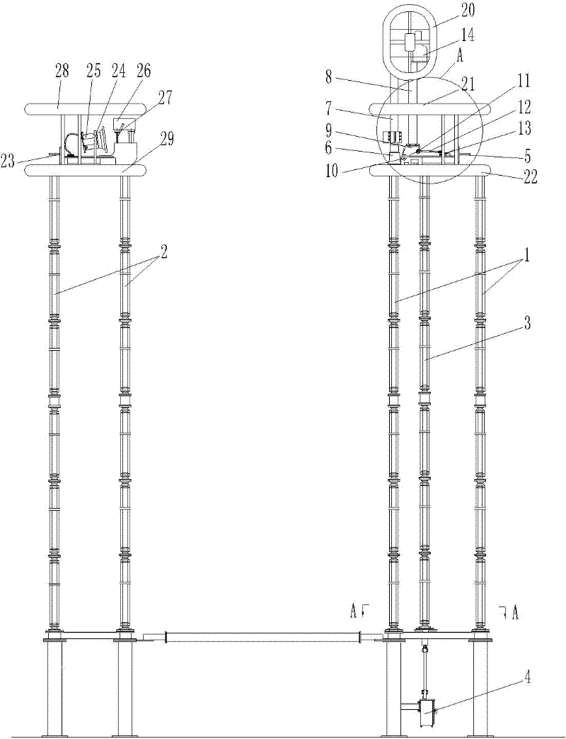
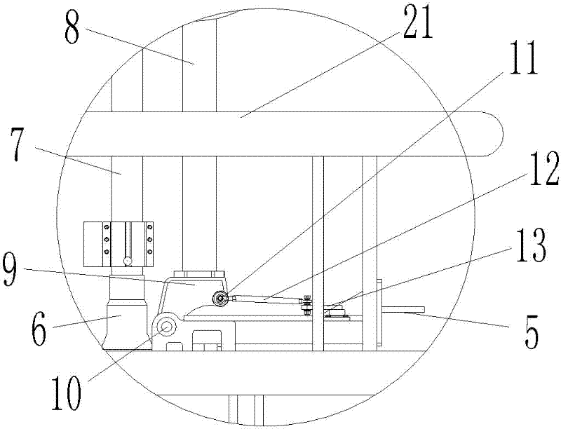
[0020] Embodiment 1 of the bypass isolating switch for 1100kV UHV series compensation of the present invention is composed of three single poles with the same structure, and the structure of each single pole is as Figure 1-5 As shown, it includes a dynamic side insulation pillar 1, a static side insulation pillar 2 and a rotating insulation pillar 3. There are three dynamic insulation pillars 1, and the three dynamic insulation pillars 1 are of equal height and distributed on the three vertices of the same regular triangle. The insulating pillar 3 is located at the center of the equilateral triangle with the position of the three moving-side insulating pillars as the apex. One of the moving-side insulating pillars is fixedly equipped with a driving device at the lower end. The driving device adopts a motor operating mechanism 4, which is operated by a motor. The moving mechanism 4 is coaxially connected with the rotating insulating support 3; the top of the moving insulating su...


PUM


Abstract

The invention relates to a bypass isolating switch for 1100-kV super-high-voltage serial compensation. The bypass isolating switch comprises three monopoles, wherein each monopole comprises a rotary insulating support, a movable side insulating support, a static side insulating support, a movable contact and a static contact, wherein the movable contact is assembled on a movable side base; a foldable retracting arm comprises a lower conductive tube and an upper conductive tube; the movable contact is fixedly assembled at the upper end of the upper conductive tube; the lower end part of the lower conductive tube is hinged on the movable side base at one side which is close to the static contact through a first hinging shaft, and is hinged with a connecting rod at one side which is far away from the static contact through a second hinging shaft; one end of the connecting rod, which is far away from the second hinging shaft, is hinged with a crank driven by the rotary insulating support; a gear box is fixedly arranged at the upper end of the lower conductive tube and the gear box is internally provided with a gear; a transmission rod is movably arranged in the lower conductive tube along the axial direction in a penetrating manner; the lower end of the transmission rod is hinged on the movable side base through a third hinging shaft; and the upper end of the transmission rod is provided with a rack engaged with the gear. The bypass isolating switch for the 1100-kV super-high-voltage serial compensation improves the stressing condition of the foldable retracting arm of the isolating switch and the normal working period is increased.

Description

Technical field [0001] The invention relates to the field of high-voltage electricity, in particular to a bypass isolation switch for 1100KV ultra-high voltage series compensation. Background technique [0002] The installation of series compensation devices on transmission lines can greatly improve the power transmission capacity of existing and newly built transmission lines and the safety and stability of the power grid. It is one of the most advanced and representative flexible AC transmission technologies. Compared with the newly built lines of the power grid, it has the characteristics of low cost, wide range of application, and energy-saving transmission corridors, which can produce good economic and social benefits, and is in line with the development direction of building a strong smart grid. The high-voltage isolating switch is an extremely important switching device in the series compensation project. It plays an isolation role in the circuit so that the maintenance pe...

Claims


Application Information

Patent Timeline
IPC IPC(8): H01H31/00H01H31/26
Inventor 王占杰孙玉洲胡延涛王巧红徐光辉马永旭夏立国尹天朔赵维全
Owner STATE GRID CORP OF CHINA
Learn More