Rotary piezoelectric power generator
A piezoelectric power generation and rotary technology, which is applied to generators/motors, piezoelectric effect/electrostrictive or magnetostrictive motors, electrical components, etc., can solve the problems of low conversion efficiency of piezoelectric energy harvesting devices, etc. Achieve the effect of improving energy collection efficiency, high energy collection efficiency, and increasing excitation frequency
- Summary
- Abstract
- Description
- Claims
- Application Information
AI Technical Summary
Problems solved by technology
Method used
Image

Examples
Embodiment 1
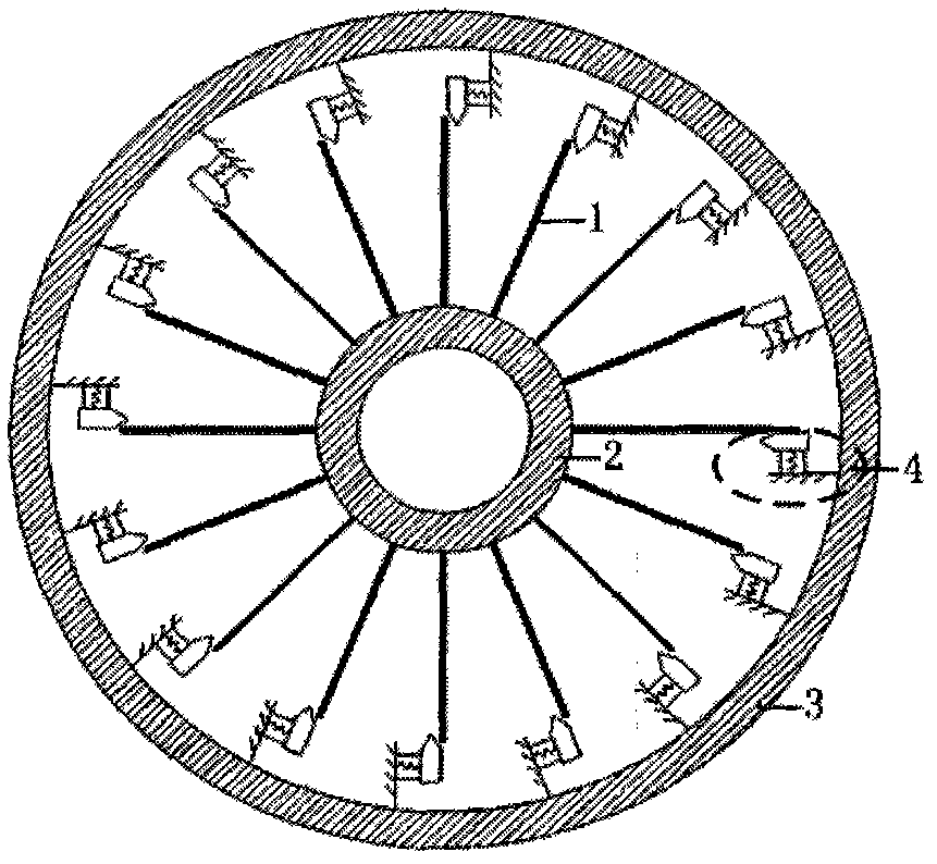
[0020] to combine figure 1 Describe this embodiment, this embodiment includes a plurality of blades 1, a shaft 2, a plurality of piezoelectric resonators 4 and a circular housing 3, and a plurality of blades 1, shafts 2, and a plurality of piezoelectric resonators 4 are installed in the circular housing 3 inside, it is characterized in that: a plurality of blades 1 are rigidly connected to the shaft 2 along the circumference of the shaft 2, and a plurality of piezoelectric resonators 4 are rigidly connected to the inner wall of the circular housing 3 along the circumference of the inner wall of the housing 3, and the shaft 2 It is coaxial with the shell 3; during the relative motion between the blade 1 and the circular shell 3, the rotating blade 1 strikes the piezoelectric resonator 4 intermittently, causing it to vibrate and deform at its natural frequency, thereby Shock loads acting on it are converted into electrical energy. The loading frequency of the piezoelectric reso...
Embodiment 2
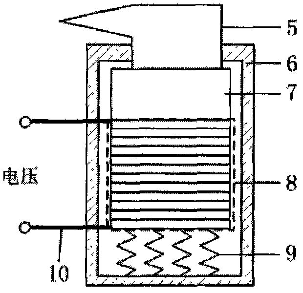
[0023] to combine figure 2 As shown, the piezoelectric resonator 4 includes an indenter 5, a peripheral sleeve 6, a mass 7, a piezoelectric stack 8, a spring 9 and a cable 10, the indenter 5 is located at the top of the peripheral sleeve 6, and is connected to the top of the peripheral sleeve 6 There is no frictional contact with the hole wall, the lower end of the indenter 5 passes through the top of the peripheral sleeve 6 and is connected to the mass block 7 inside the peripheral sleeve 6, the mass block 7 is connected to the piezoelectric stack 8, and one end of the spring 9 is fixed to the end of the piezoelectric stack 8 At the bottom end, the other end of the spring 9 is fixed on the bottom end of the peripheral sleeve 6; the upper and lower ends of the piezoelectric stack 8 are electrically connected to the two terminals of the cable 10 respectively, and the connection is insulated and protected by epoxy resin; the two ends of the cable 10 A terminal protrudes outside...
Embodiment 3
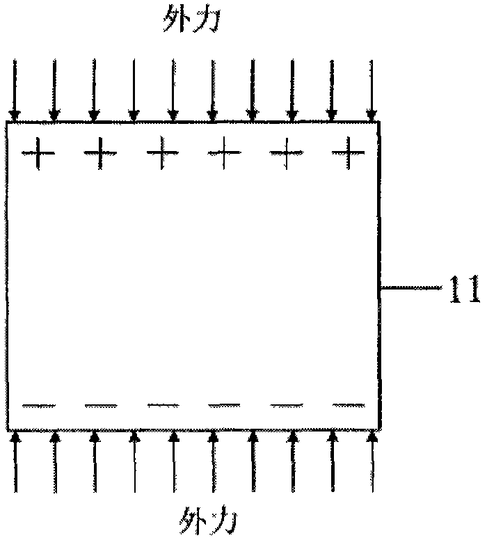
[0030] to combine Figure 4 Explain the composition of the piezoelectric stack structure. The piezoelectric sheets 11 and the electrodes 12 are alternately arranged to form a piezoelectric stack 8, wherein the polarization directions of two adjacent piezoelectric sheets are opposite, so that the piezoelectric sheets 11 are in a series structure mechanically. Electrically, it is a parallel structure, so that the generated voltage value is relatively low, which is convenient for management in the circuit.
PUM
 Abstract
Description
Claims
Application Information
 - R&D
- Intellectual Property
- Life Sciences
- Materials
- Tech Scout
- Unparalleled Data Quality
- Higher Quality Content
- 60% Fewer Hallucinations
Browse by: Latest US Patents, China's latest patents, Technical Efficacy Thesaurus, Application Domain, Technology Topic, Popular Technical Reports.
© 2025 PatSnap. All rights reserved.Legal|Privacy policy|Modern Slavery Act Transparency Statement|Sitemap|About US| Contact US: help@patsnap.com