Compound energy collecting circuit

A technology for collecting circuits and composite energy, which is applied in the direction of current collectors, circuit devices, battery circuit devices, etc., can solve the problems of affecting collection efficiency, collection efficiency load impact, and low circuit collection efficiency, so as to reduce the cost of use and improve energy collection efficiency effect

Active Publication Date: 2018-06-29
NINGBO UNIV
View PDF7 Cites 6 Cited by
  • Summary
  • Abstract
  • Description
  • Claims
  • Application Information

AI Technical Summary

Problems solved by technology

[0002] Piezoelectric vibration energy collection is a method of collecting vibration energy in the environment by using the piezoelectric effect of piezoelectric materials. Since the output voltage of the piezoelectric sheet is an AC signal, the general electronic equipment is powered by a DC power supply. Therefore, an interface circuit is needed between the piezoelectric film and the electronic device, and the conversion of AC voltage to DC voltage is realized through the interface circuit, and the conversion efficiency of this interface circuit is as high as possible. The first proposed interface circuit It is a standard energy harvesting circuit, which is composed of a diode bridge rectifier circuit and a filter capacitor. The advantage of this structure is that the circuit is simple, stable and reliable. However, due to the loss of the threshold voltage of the diode, the acquisition efficiency of the circuit is low, and this The acquisition efficiency of the structure is easily affected by the size of the load
[0003] The thermoelectric power generation chip can use the temperature difference in the environment to collect energy, but usually the temperature difference in the environment is small, the open circuit voltage of the thermoelectric power generation chip is very low, and factors such as the efficiency of the energy harvesting circuit between the power generation chip and the load increase the temperature difference energy. Difficulty in utilization; current thermoelectric energy collection circuits are mainly divided into capacitive charge pump circuits and inductive boost circuits. Although the charge pump circuit can increase the voltage of the thermoelectric power generation chip, the drive capability of the charge pump structure is very weak, and the low-voltage charge pump The circuit is even more inefficient; although the inductive boost circuit has high efficiency and strong ability to drive the load, the open circuit voltage of the general thermoelectric power generation chip is lower than the threshold voltage of the switch tube, which leads to the boost structure often requiring an external power supply , when the external power supply is not connected, it cannot start automatically, which increases the cost of use
[0004] In order to obtain more energy from the environment and increase the total power of environmental energy collection, some researchers have proposed the idea of ​​multi-source energy collection, that is, to collect various forms of energy such as vibration energy, thermal energy, and microwave radiation in the environment. However, since the signals generated by different energy sources are completely different, different signals cannot be directly coupled together, so the general multi-source energy harvesting system usually adopts the comparison method, that is, by comparing the two energy densities to select the one with the stronger energy. One kind of energy, so another kind of energy cannot be collected, affecting the overall collection efficiency

Method used


Image

  • Compound energy collecting circuit
  • Compound energy collecting circuit

Examples


Embodiment Construction

[0011] The present invention will be further described in detail below in conjunction with the accompanying drawings and embodiments.

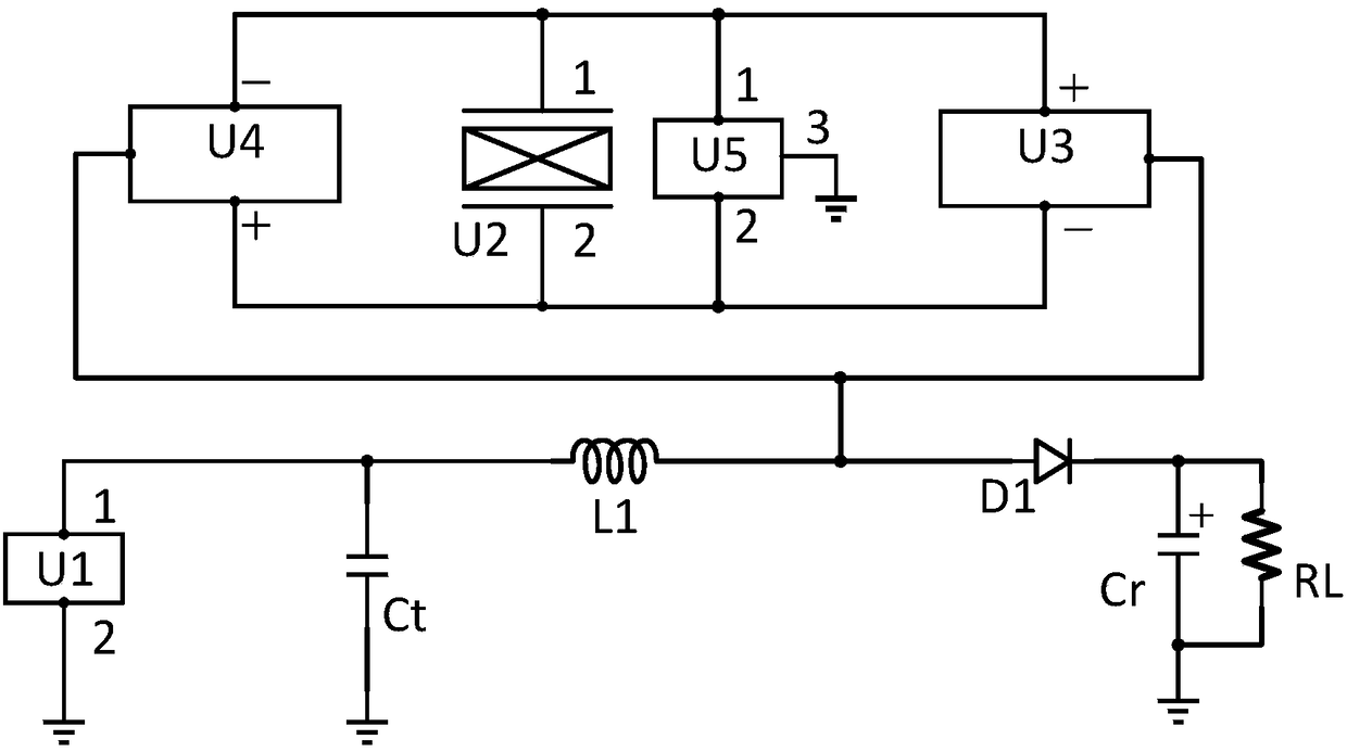
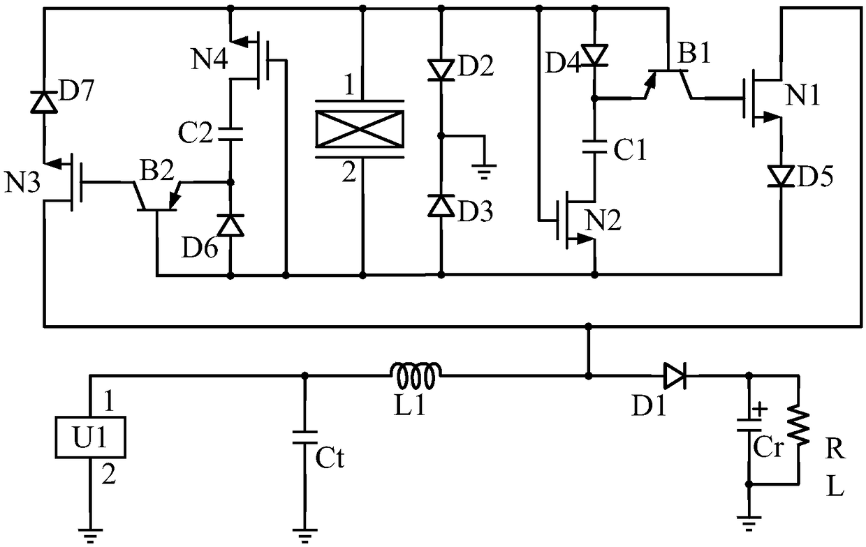
[0012] A composite energy collection circuit, comprising a thermoelectric power generation sheet U1, a piezoelectric sheet U2, a positive peak detection module U3, a negative peak detection module U4, a zero potential switching module U5, a first inductor L1, a first diode D1, a first The energy storage capacitor Ct, the second energy storage capacitor Cr and the load RL are connected to the first pin of the thermoelectric generator U1, one end of the first energy storage capacitor Ct and one end of the first inductance L1, and the other end of the first inductance L1, The input terminal of the positive peak detection module U3, the input terminal of the negative peak detection module U4 and the anode of the first diode D1 are connected, the negative pole of the first diode D1, the positive pole of the second energy storage capacitor Cr and one...


PUM


Abstract

The invention discloses a compound energy collecting circuit. The compound energy collecting circuit is characterized by comprising a temperature difference power generation sheet, a piezoelectric sheet, a positive peak detection module, a negative peak detection module, a zero potential switching module, a first inductor, a first diode, a first energy storage capacitor, a second energy storage capacitor and a load. The compound energy collecting circuit has the advantages that when voltage at the two ends of the piezoelectric sheet reaches the peak, a switching tube is switched on through thepeak detection modules, so that the circuit generates LC oscillation, thus charges on a stray capacitor in the piezoelectric sheet and charges accumulated on the first energy storage capacitor are transferred to the first inductance, at the moment when current on the first inductance reaches the maximal value, a first NMOS pipe is immediately switched off through the positive peak detection module, or a third NMOS pipe is immediately switched off through the negative peak detection module, energy stored on the first inductor all flows to the load and the second energy storage capacitor through the first diode, the whole circuit is completely supplied with power by itself, and the energy collecting efficiency is high.

Description

technical field [0001] The invention relates to an energy collection circuit, in particular to a composite energy collection circuit. Background technique [0002] Piezoelectric vibration energy collection is a method of collecting vibration energy in the environment by using the piezoelectric effect of piezoelectric materials. Since the output voltage of the piezoelectric sheet is an AC signal, the general electronic equipment is powered by a DC power supply. Therefore, an interface circuit is needed between the piezoelectric film and the electronic device, and the conversion of AC voltage to DC voltage is realized through the interface circuit, and the conversion efficiency of this interface circuit is as high as possible. The first proposed interface circuit It is a standard energy harvesting circuit, which is composed of a diode bridge rectifier circuit and a filter capacitor. The advantage of this structure is that the circuit is simple, stable and reliable. However, du...

Claims


Application Information

Patent Timeline
Patent Type & Authority Applications(China)
IPC IPC(8): H02N2/18H02N11/00H02J7/32
CPCH02J7/32H02J7/345H02J15/00
Inventor 夏银水王修登施阁叶益迭钱利波夏桦康
Owner NINGBO UNIV
Why Eureka
Try Eureka