Method for functionally checking a vacuum switch of a traction inverter

A technology for traction converters and vacuum switches, which is applied in circuit breaker testing, high-voltage/high-current switches, electric switches, etc. It can solve problems such as complexity, damage to vacuum switches, and occupying the downtime of traction drive devices, so as to simplify faults The detection method is simple and easy, and the effect of fault detection is improved

Active Publication Date: 2012-08-22
SIEMENS MOBILITY GMBH
View PDF3 Cites 0 Cited by
  • Summary
  • Abstract
  • Description
  • Claims
  • Application Information

AI Technical Summary

Problems solved by technology

[0008] This test of the vacuum switch is complex and takes traction drive downtime
If not tested, failure of a vacuum switch can lead to serious subsequent damage
The function test of the vacuum switch requires the use of test equipment and can therefore only be carried out in the parking lot of a railway or tram

Method used


Image

  • Method for functionally checking a vacuum switch of a traction inverter
  • Method for functionally checking a vacuum switch of a traction inverter
  • Method for functionally checking a vacuum switch of a traction inverter

Examples


Embodiment Construction

[0016] The invention and the principle of operation of the method according to the invention will be described in detail below with the aid of the drawings.

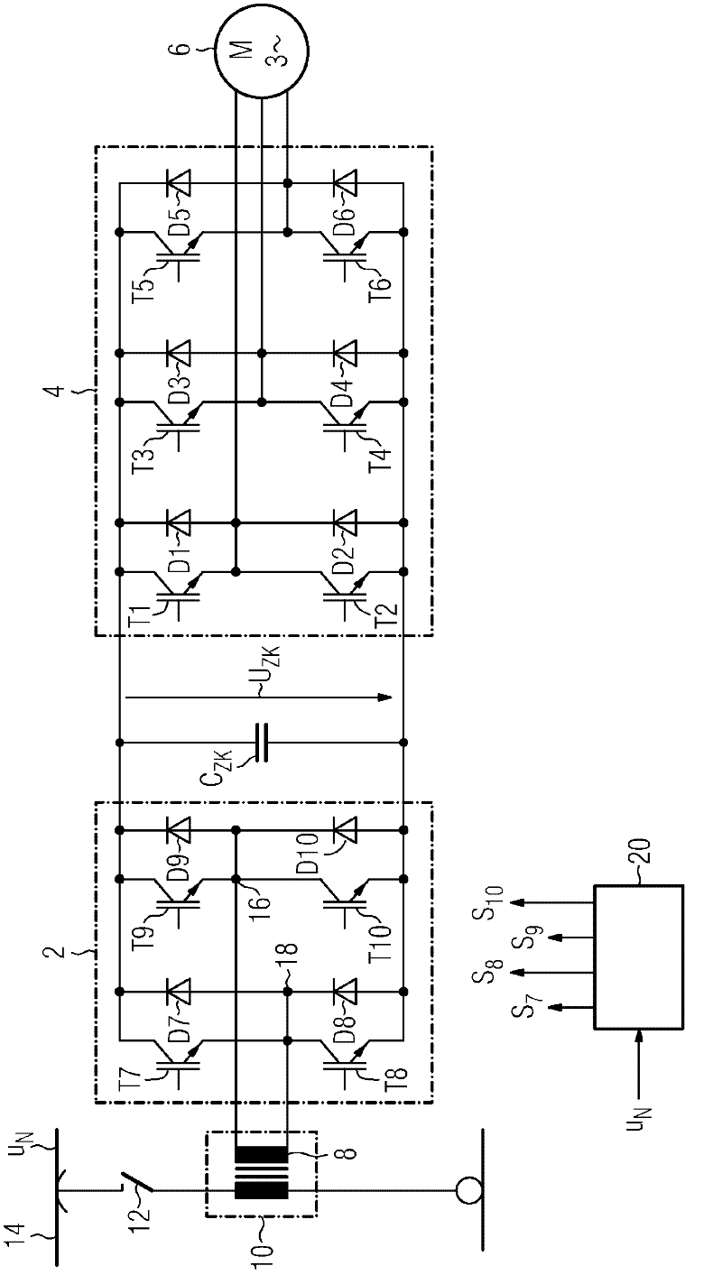
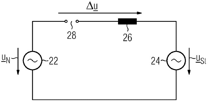
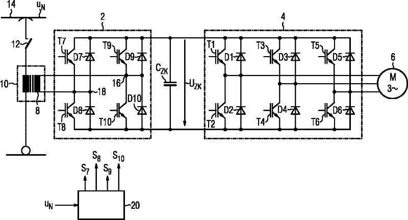
[0017] This single-phase equivalent circuit diagram has a voltage source 22 and a voltage source 24 connected in parallel. A voltage source 22 replaces the grid, a voltage source 24 replaces the DC voltage side with an intermediate circuit capacitor C ZK The four-quadrant chopper 2. This single-phase equivalent circuit diagram only shows the leakage inductance 26 of the traction transformer 10 . An open vacuum switch 12 is shown in the equivalent circuit diagram as a spark gap 28 . The vacuum switch 12 is closed during operation of the traction converter, and the two voltage sources 22 and 24 are electrically connected in parallel via the leakage inductance of the traction transformer 10 . As shown in the equivalent circuit diagram, the grid AC voltage u N with chopper input voltage u St are phase shifted relative...


PUM


Abstract

The invention relates to a method for functionally checking a vacuum switch (12) of a traction inverter having at least one grid-side four quadrant chopper (2) and a load-side pulse inverter (4) electrically connected in parallel on the DC side by means of an intermediate circuit capacitor (CZK), and having a traction transformer (10) having at least one secondary winding (8), the connections thereof being linked to AC side connections (16,18) of the four quadrant chopper (2), and the primary winding thereof being able to be connected to a connection by means of the vacuum switch (12) to an AC grid voltage (uN). According to the invention, the four quadrant chopper (2) is actuated when the vacuum switch is open (12) precisely when the AC grid voltage (uN) is temporally located relative to the chopper input voltage (USt), such that the amplitude of a differential voltage delta u) between the AC grid voltage (uN) and the chopper input voltage (USt) corresponds to a predetermined test voltage, wherein a check is subsequently made whether current flows from the supplying grid to the four quadrant chopper (2). The functionality of a vacuum switch (12) of a traction inverter can thereby be performed at any time without a test device.

Description

technical field [0001] The invention relates to a method for functional testing of a vacuum switch of a traction converter. Background technique [0002] This type of traction converter is detailed in figure 1 . The traction converter has a four-quadrant chopper 2 on its AC supply side and an automatically commutated converter 4, also called a pulse converter, on its load side, the DC voltage side of these two components is connected by means of an intermediate circuit capacitor C ZK electrically connected in parallel. The output end of the pulse converter 4 is connected to a three-phase AC motor 6 . The AC voltage side of the four-quadrant chopper 2 can be electrically conductively connected to the contact line 14 by means of the secondary winding 8 of the traction transformer 10 and the vacuum switch 12 . The secondary windings 8 of the traction transformer 10 each have one terminal connected in an electrically conductive manner to the AC voltage terminals 16 and 18 o...

Claims


Application Information

Patent Timeline
Patent Type & Authority Applications(China)
IPC IPC(8): H01H33/66G01R31/327B60L9/00
CPCB60L3/0023B60L9/00B60L2200/26G01R31/008G01R31/3275G01R31/42H01H33/66H01H33/668
Inventor 诺贝特·朗格
Owner SIEMENS MOBILITY GMBH
Why Eureka
Try Eureka