Nozzle surface cleaning device and ink-jet recording device

A cleaning device and inkjet recording technology, which is applied in the field of head cleaning, can solve the problems of long time for wiping parts to be wet, damage of lyophobic film, inability to solve cleaning liquid uniformity, cleaning liquid liquid dripping, etc. The effect of stability

Inactive Publication Date: 2012-08-29
FUJIFILM CORP
View PDF2 Cites 20 Cited by
  • Summary
  • Abstract
  • Description
  • Claims
  • Application Information

AI Technical Summary

Problems solved by technology

[0012] On the other hand, in the technique of Patent Document 1, the washing liquid can be uniformly impregnated, but since a small amount of washing liquid is supplied to the wiping member, there is a disadvantage that it takes a long time for the wiping member to spread evenly until it becomes wet.
In addition, since the fog floats, there is also a problem of polluting the inside of the facility
[0013] In addition, in Patent Document 2, the uniformity of the cleaning liquid in the wiping member and the problem of liquid dripping caused by excessive cleaning liquid cannot be solved.
In addition, when wiping is performed without supplying the cleaning liquid, there is also a problem that the liquid-repellent film on the nozzle surface of the head is damaged.

Method used


Image

  • Nozzle surface cleaning device and ink-jet recording device
  • Nozzle surface cleaning device and ink-jet recording device
  • Nozzle surface cleaning device and ink-jet recording device

Examples


no. 1 approach

[0030] (Apparatus Configuration of Inkjet Recording Apparatus)

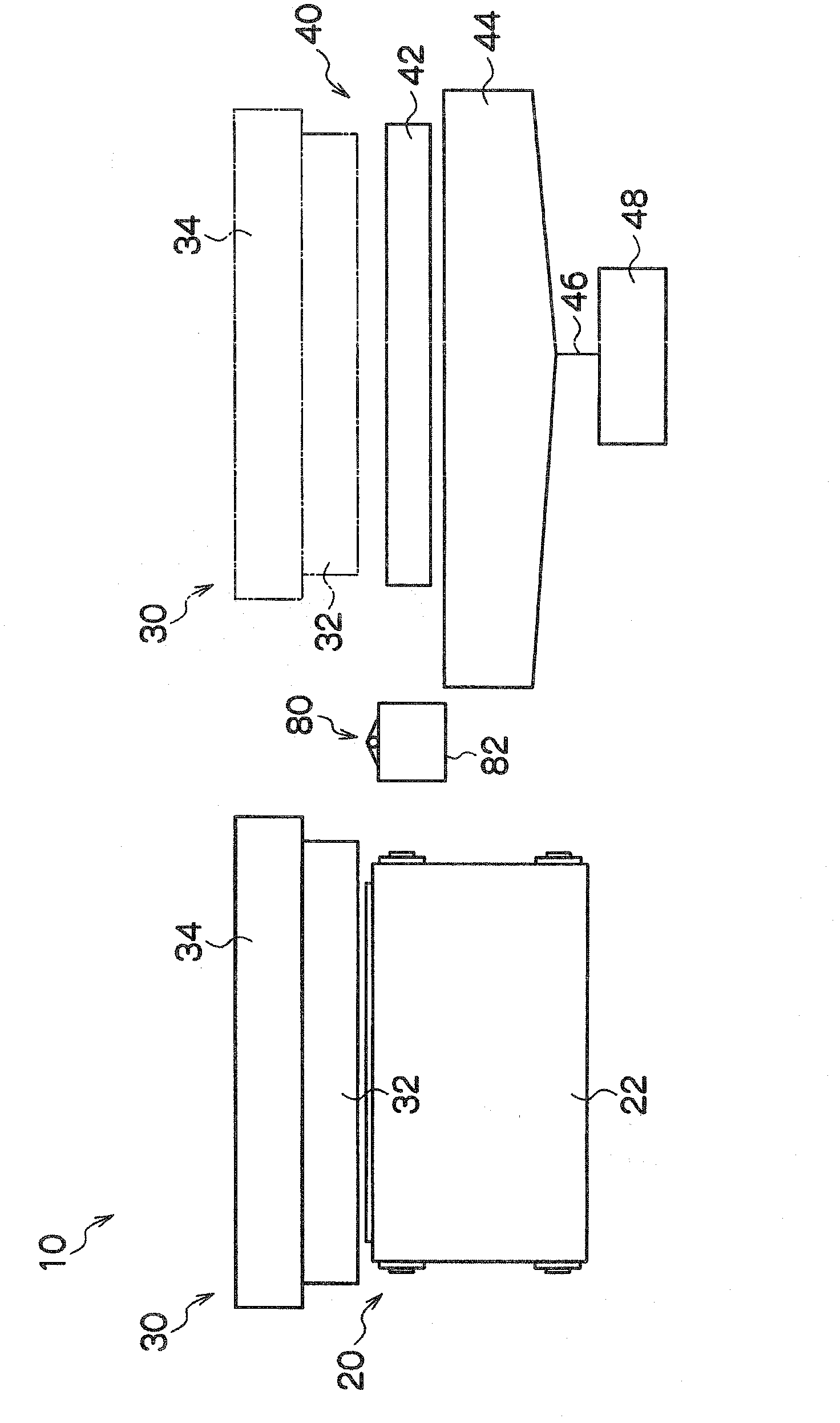
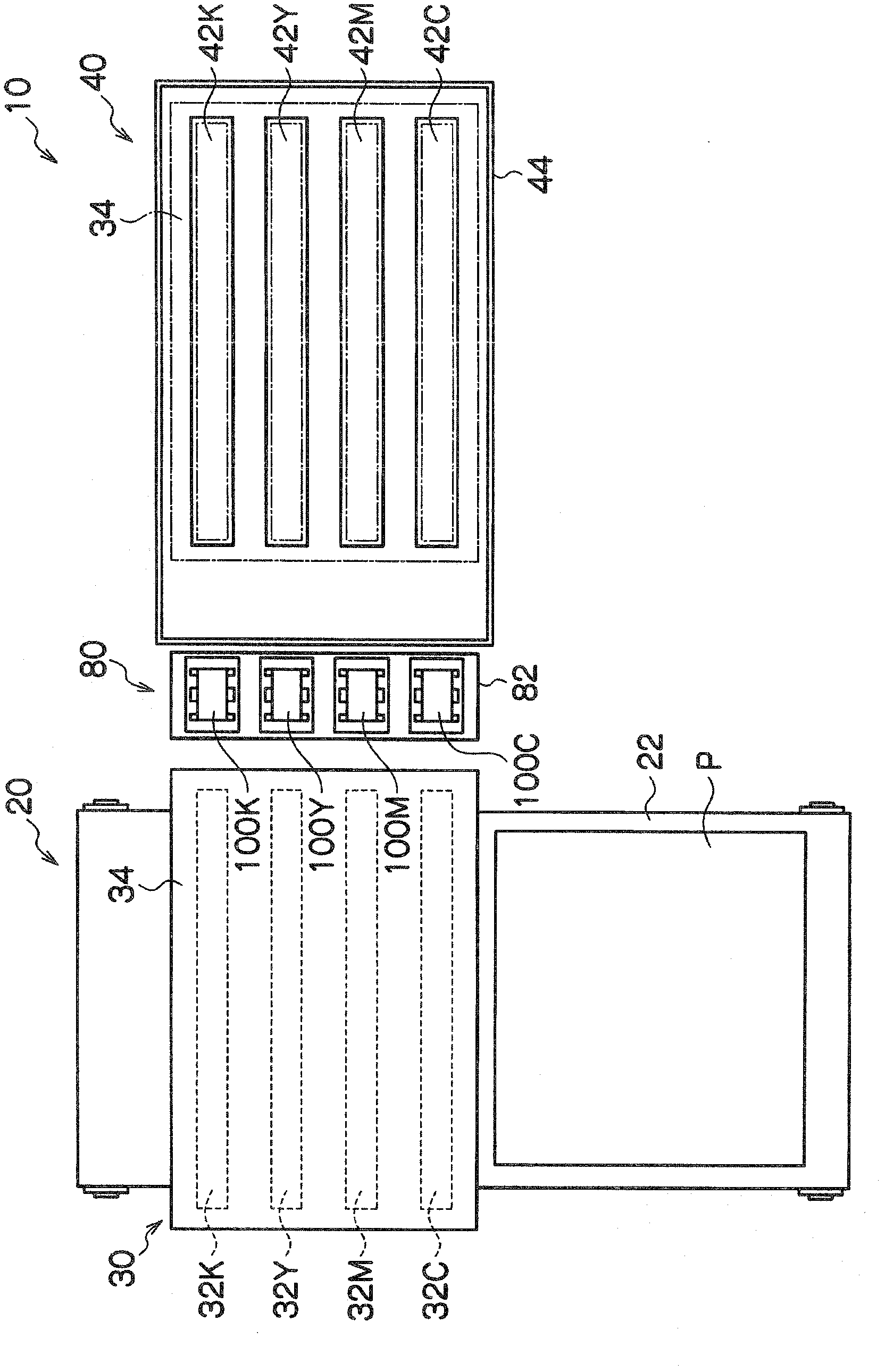
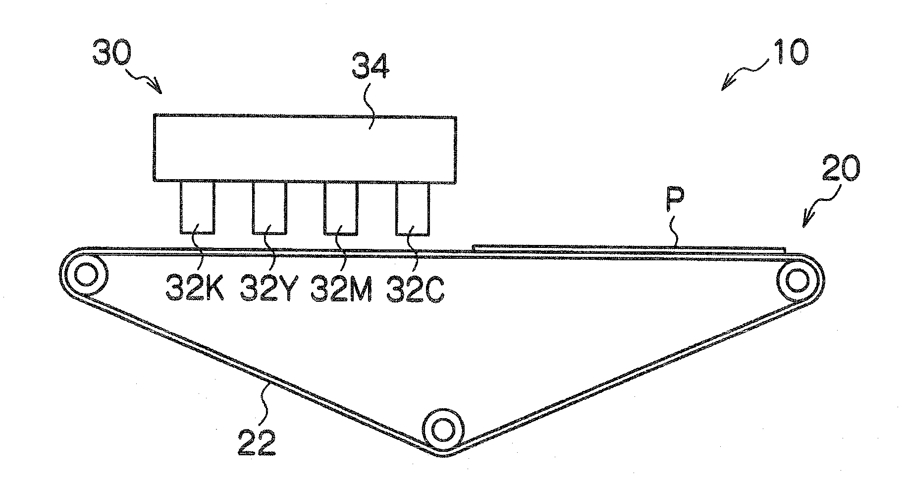
[0031] Figure 1 ~ Figure 3 It is a front view, a plan view, and a side view showing the configuration of main parts of the inkjet recording apparatus according to this embodiment.

[0032] as it should Figure 1~3 As shown, the inkjet recording device 10 is a single-pass type line printing machine, and mainly ejects to the paper P conveyed by the paper conveying mechanism 20 by a paper conveying mechanism 20 that conveys a recording medium, that is, a paper (sheet) P. The head unit 30 for cyan (C), magenta (M), yellow (Y), and black (K) ink droplets of each color, the maintenance unit 40 for performing maintenance of each head mounted on the head unit 30 , and the cleaning unit 40 mounted on the The nozzle surface cleaning device 80 of the nozzle surface of each head of the head unit 30 is comprised.

[0033] The paper conveying mechanism 20 is constituted by a belt conveying mechanism, and makes the moving b...

no. 2 approach

[0108] Next, a second embodiment of the present invention will be described. In addition, in the following description, description of the same configuration as that of the above-mentioned first embodiment will be omitted. In the first embodiment, the remaining cleaning solution for wiping the web is recovered by suction with the recovery pump, but in the second embodiment, the remaining cleaning solution for wiping the web is recovered by pressing with the squeezing mechanism .

[0109] Figure 6 It is a schematic diagram which shows the schematic structure of the wiping off unit 100 of this embodiment. as it should Figure 6 As shown, the cleaning liquid recovery part 150 of the wiping unit 100 is provided with a pair of squeeze rollers 170 and a push adjustment roller instead of the recovery roller 152, the third guide roller 154, and the fourth guide roller 156 of the cleaning liquid recovery part 150 of the first embodiment. Mechanism 172 and recovery receiving part 1...

no. 3 approach

[0118] Next, a third embodiment of the present invention will be described. In addition, in the following description, the description of the same configuration as the above-mentioned embodiment is omitted. In this embodiment, the remaining cleaning liquid is recovered by evaporating using the air blowing mechanism and the temperature raising mechanism.

[0119] Figure 7 It is a schematic diagram which shows the schematic structure of the wiping off unit 100 of this embodiment. as it should Figure 7 As shown, the cleaning liquid recovery unit 150 of the wiping unit 100 includes a blower fan 180 (air blower mechanism), a suction fan 182, and a heating plate 184 (heating mechanism).

[0120] The blower fan 180 is a blower mechanism for evaporating the washing liquid applied to the wiping roll paper 112 . The blower fan 180 is configured to have a width corresponding to the width of the wiping paper roll 112, is arranged above the wiping paper roll 112, and can blow air dow...


PUM


Abstract

The dripping of washing liquid and the infiltration of washing liquid from a nozzle surface of a head when the nozzle surface is wiped is suppressed and discharge stability is improved. A wiping unit (100) includes a conveying portion (110) for conveying a wiping web (112), a washing liquid supplying portion (140) for supplying washing liquid to the wiping web, and a washing liquid collecting portion (150) for collecting washing liquid from the wiping web to which washing liquid has been supplied. After washing liquid is supplied to the wiping web, which is conveyed by the conveying portion, at washing liquid supplying portion, surplus washing liquid is collected from the wiping web at the washing liquid collecting portion. The wiping web from which washing liquid has been collected is wound on a pressure roller (122) and comes into press contact with the nozzle surface of the head, thereby wiping web wipes and cleans the nozzle surface.

Description

technical field [0001] The present invention relates to a nozzle surface cleaning device and an inkjet recording apparatus, and particularly relates to a head cleaning technique for wiping the nozzle surface of an inkjet head with a wiping member to which cleaning liquid is applied. Background technique [0002] In an inkjet recording device, when the nozzle surface (the surface on which the nozzle is formed) of the nozzle is contaminated, ejection failure occurs. Therefore, it is necessary to regularly clean the nozzle surface. [0003] As a method of cleaning the nozzle surface, a method of wiping the nozzle surface with a scraper, a method of wiping the nozzle surface with a web, and the like are conventionally known. [0004] Patent Document 1 discloses a technique in which, when spraying a cleaning liquid on a frictional contact sheet for wiping the nozzle surface of a droplet ejection head, a masking mechanism is used to delineate the spraying area of ​​the cleaning l...

Claims


Application Information

Patent Timeline
Patent Type & Authority Applications(China)
IPC IPC(8): B41J2/165
CPCB41J2/16552B41J2/16588B41J2002/16558
Inventor 井上浩志
Owner FUJIFILM CORP
Why Eureka
Try Eureka