Liquid control check valve

A single-flow valve and hydraulic control technology, which is applied in wellbore/well valve devices, wellbore/well components, earthwork drilling and production, etc., can solve problems affecting oil well pump maintenance operations, affecting construction effects, and sealing device failure, etc. problems, to achieve the effect of convenient daily maintenance work, simple structure and saving construction costs

Active Publication Date: 2015-07-08
PETROCHINA CO LTD
View PDF6 Cites 0 Cited by
  • Summary
  • Abstract
  • Description
  • Claims
  • Application Information

AI Technical Summary

Problems solved by technology

[0010] 1. The existing hollow polished rod is directly connected with the hollow rod, and the thermal working medium in the hollow rod may return to the hollow polished rod and overflow from the upper end of the hollow polished rod, which will pollute the environment
[0011] 2. Once step D is entered, if the sealing device at the top of the hollow polished rod leaks for rectification, it is necessary to let go of the thermal fluid in the hollow rod, and then re-evacuate the hollow rod, which will not only affect the working time, but also pollute surroundings
[0012] 3. When starting the pumping unit, if the length of the hollow polished rod outside the wellhead is not adjusted well, the top sealing device of the hollow polished rod will easily collide with the donkey head of the pumping unit, and the sealing device will fail in severe cases At this time, the sealing device cannot be removed and reinstalled. After a leak, it must be vacuumed and heated again, which seriously affects the construction effect, and also affects the daily maintenance operations such as touching the pump of the oil well.

Method used


Image

  • Liquid control check valve
  • Liquid control check valve
  • Liquid control check valve

Examples


Embodiment Construction

[0038] The following will clearly and completely describe the technical solutions in the embodiments of the present invention with reference to the accompanying drawings in the embodiments of the present invention. Obviously, the described embodiments are only some, not all, embodiments of the present invention. Based on the embodiments of the present invention, all other embodiments obtained by persons of ordinary skill in the art without making creative efforts belong to the protection scope of the present invention.

[0039] The upper or lower position described in this article refers to the use state of the hydraulic control check valve after entering the downhole. To be precise, the upper joint position of the hydraulic control check valve is up and the lower joint position is down .

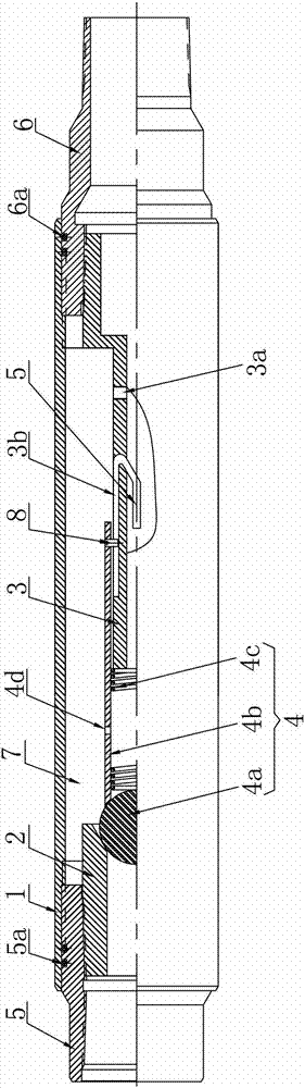
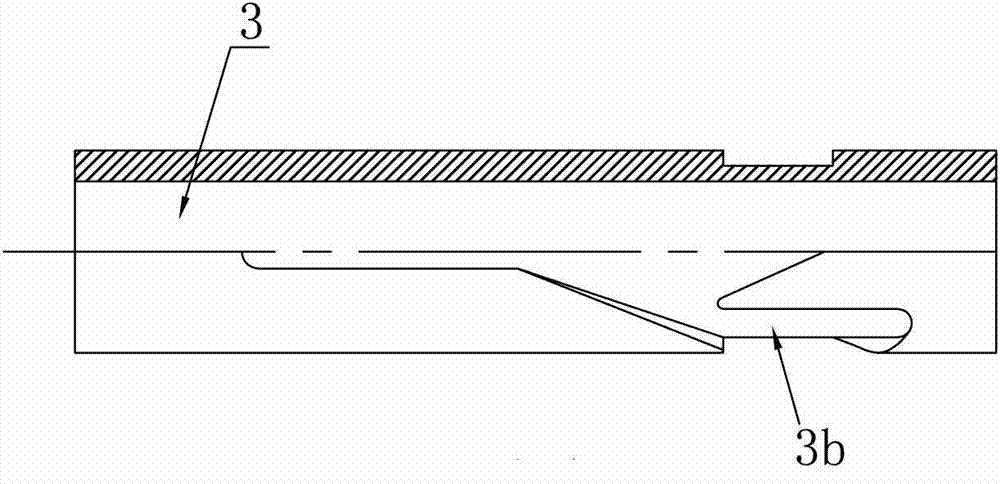
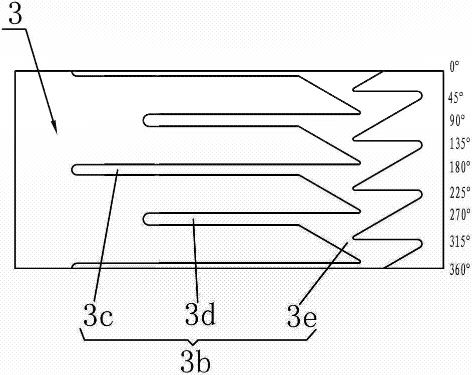
[0040] like figure 1 and figure 2 As shown, the hydraulic control check valve proposed by the embodiment of the present invention is connected between the hollow polished rod and the hol...


PUM


Abstract

The invention discloses a liquid control check valve which is connected between a hollow polish rod and a hollow sucker rod, and comprises a sleeve, a valve ball seat, a centrode tube and a valve ball component, wherein the upper end of the sleeve is provided with an upper joint which is used for connecting with the hollow polish rod, and the lower end of the sleeve is provided with a lower joint for connecting with the hollow sucker rod; the valve ball seat is arranged at the inner side of the upper part of the sleeve; the centrode tube is arranged at the inner side of the lower part of the sleeve, a flow passage is arranged between the centrode tube and the valve ball seat, and a first through hole is arranged at the wall of the centrode tube; and the valve ball component comprises a valve ball, a sliding sleeve and a spring, the sliding sleeve is fixedly connected with the lower part of the valve ball, the spring is positioned in the sliding sleeve and propped between the valve ball and the centrode tube, the sliding sleeve can be vertically, movably connected with the outer side of the upper end of the centrode tube, and the valve ball can be tightly coupled with the valve ball seat.

Description

technical field [0001] The invention relates to a check valve, in particular to a hydraulically controlled check valve used in the field of heavy oil and super heavy oil exploitation. Background technique [0002] Gravity heat pipe wellbore heat tracing viscosity reduction technology has a certain application value, it can prolong the production cycle of steam huff and puff oil wells, increase the cycle production of oil wells, and reduce energy consumption. [0003] The construction steps of gravity heat pipe wellbore heat tracing and viscosity reduction technology are as follows: [0004] A. The operation team completes the well, lowers the hollow sucker rod (also known as the hollow rod), and connects the hollow polished rod to the upper end of the hollow rod, and adjusts the length of the hollow polished rod outside the wellhead to facilitate the operation of the operator in the next step; [0005] B. Install a thermal fluid injection device on the upper end of the holl...

Claims


Application Information

Patent Timeline
Patent Type & Authority Patents(China)
IPC IPC(8): E21B34/00
Inventor 王书慧管九洲郎宝山
Owner PETROCHINA CO LTD
Why Eureka
Try Eureka