Loess layer-based dry drilling tunneling method and equipment

A loess layer, dry drilling technology, applied in drilling equipment, drilling equipment and methods, earthwork drilling and mining, etc., can solve the problems of cuttings difficult to take out of the ground, recurring leakage, prone to downhole accidents, etc., to avoid environmental pollution Accidents, the effect of solving leakage problems

Active Publication Date: 2021-03-16
BC P INC CHINA NAT PETROLEUM CORP +1
View PDF5 Cites 0 Cited by
  • Summary
  • Abstract
  • Description
  • Claims
  • Application Information

AI Technical Summary

Problems solved by technology

Using this method requires a drilling rig, a large-displacement air compressor, a supercharger, and a down-the-hole hammer. Drill sticking accidents are prone to occur when drilling in cement or wet soil. At the same time, it takes a long time to complete multiple equipments and high costs, and it is difficult to apply on a large scale. Method When drilling into the clay layer, cuttings are difficult to bring out of the ground, and downhole accidents are prone to occur;
[0006] Eye expander: The working principle is to reduce the penetration rate of clear water in the loess by strengthening the density of the loess layer on the well wall. This method has undergone three iterations from the hollow straight-edged eye expander to the petal-type eye expander, and then to the hollow without edge Type eye expander, the disadvantage is that it cannot deal with the clay layer, large cracks and caves in the loess layer;
[0007] Catheter bottom plug: the working principle is that the conduit is lowered into the bottom of the well, the suspended weight is released, the copper pin is cut off, the conduit nipple and the sliding sleeve slide relative to each other, and the rubber tube expands in the axial direction of pressure, forming an annular sealing ring to seal the upper and lower In the annulus, using this method, the sliding sleeve of the bottom plug of the conduit, that is, the maximum outer diameter of 380mm, is only 35mm away from the single side of the follow-up 311 wellbore. Due to the difference in compaction strength of the loess layer itself and the erosion of the drilling fluid, the conduit will basically sink to varying degrees. 10-15 cm away from the well wall, the isolation time is short, and it is easy to be soaked and washed by the drilling fluid to cause recurring leakage. At the same time, the outer diameter and shape of the sliding sleeve cannot meet the actual needs of loess layer leakage prevention

Method used


Image

  • Loess layer-based dry drilling tunneling method and equipment
  • Loess layer-based dry drilling tunneling method and equipment
  • Loess layer-based dry drilling tunneling method and equipment

Examples


Embodiment 1

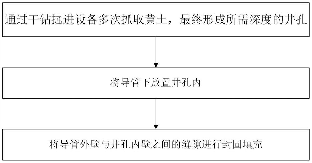
[0053] refer to figure 1 , is a schematic diagram of the dry drilling and excavation steps based on the loess layer of the present invention, a dry drilling and excavation method based on the loess layer, comprising the following steps

[0054] Step 1: Dry Drilling

[0055] Dry drilling is carried out by dry drilling equipment to form a wellbore of required depth;

[0056] Step 2: down the catheter

[0057] Place the catheter down the wellbore;

[0058] Step 3: Seal the inner and outer rings

[0059] Seal and fill the gap between the outer wall of the conduit and the inner wall of the wellbore.

[0060] The above-mentioned implementation is based on a drilling method that does not require fluid medium circulation in the drilling construction of the loess layer, because the loess layer is a special stratum structure, wherein the stratum structure is loose and has natural fractures on the surface of the loess layer, and at the same time There will also be stratum structures...

Embodiment 2

[0063] In the further described step one, the specific construction method of dry drilling and excavation includes

[0064] First install the digging device in the dry drilling equipment directly above the well hole to be drilled;

[0065] Adjust the center position of the digging device to correspond to the center position of the borehole to be drilled;

[0066] The driving device in the dry drilling excavation equipment is started, and the excavating device is driven by the driving device to carry out dry drilling and excavation.

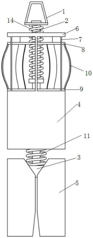
[0067] Further, the dry drilling excavation is that the excavating device is started by the driving device and then freely falls downwards by its own weight, rushes to the ground and penetrates into the soil layer through the downward free fall movement, and then grabs the loess.

[0068] Further, after grabbing the loess, the driving device drives the digging device to move upwards. After moving out of the well hole, the digging device is locate...

Embodiment 3

[0071] Further, in step 2, the conduit is lowered into the wellbore and a hanging device is used to hang the conduit into the wellbore excavated by dry drilling.

[0072] Further, before using the hanging device to hang the conduit into the well hole that is driven in and out by dry drilling, there is also a conduit stopper bracket at the well hole, and the inner diameter of the conduit stopper bracket is larger than the diameter of the wellbore.

[0073] When the conduit is suspended, a gap of 300 mm to 500 mm is preferably left between the bottom of the conduit and the bottom of the well.

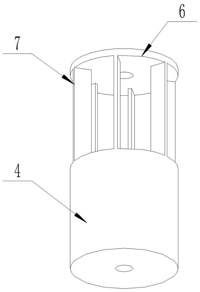
[0074] The conduit adopts PE400 corrugated drainage pipe.

[0075] In this embodiment, when the pipe is lowered, it is necessary to use a hanging device to hang the pipe into the well hole through the dry drilling. There is a sling on the top, and the sling on the hanging device is connected to the clamp and the rope tightener. Specifically, the tube is clamped by the clamp connected to ...


PUM

PropertyMeasurementUnit
thicknessaaaaaaaaaa
thicknessaaaaaaaaaa

Abstract

The invention relates to the technical field of petroleum drilling construction, in particular to a loess layer-based dry drilling tunneling method and equipment. In a drilling method adopted in drilling construction in a loess layer, fluid medium circulation construction is not needed; an existing drilling method cannot meet the drilling requirement of the loess layer; and even if the drilling succeeds, in actual application, the situation of leakage occurs in wells based on the existing drilling method, and leaked drilling fluid directly flows into rivers and farmlands, thereby causing different degrees of environmental pollution; and therefore the problem of loess layer leakage is hard to thoroughly solve through the existing traditional drilling process method. According the dry drilling tunneling method, the dry drilling tunneling equipment is adopted for dry tunneling, so a well hole with the needed depth is formed; then the guide pipe is placed in the well hole, and environment-friendly well cementation is adopted; and slurry circulation is not needed in the drilling process, water is not needed in the well cementation process, the leakage problem is fundamentally solved, and environmental pollution accidents are avoided.

Description

technical field [0001] The invention relates to the technical field of oil drilling construction, in particular to a loess layer-based dry drilling method and equipment. Background technique [0002] In the drilling construction of the loess layer, the surface structure of the loess is loose and there are natural fractures, which is prone to lost circulation. The plugging affects the drilling efficiency. When the lost circulation is serious, the derrick foundation sinks, and the drilling fluid leaks out of the well site through the cracks on the surface, causing environmental pollution. . [0003] And the existing drilling construction is divided into inflatable drill, air drill, eye expander, conduit bottom plug etc. to carry out drilling, wherein [0004] Air-filled drill: Air compressor and air storage tank are required. The air-filled pipeline is connected to the air source through a self-made check valve and conversion joint. It is necessary to configure micro-bubble t...

Claims


Application Information

Patent Timeline
Patent Type & Authority Applications(China)
IPC IPC(8): E21B11/00E21B27/00E21B19/08E21B33/13E21B33/138C08G18/48C08L75/08
CPCE21B11/00E21B27/00E21B19/08E21B33/13E21B33/138C08G18/48C08L75/08Y02P20/141
Inventor 王伟良张建卿李雪岗侍德益李德波胡祖彪朱明明王清臣韩成福张健袁立志张延兵谭学斌焦武山胡延霞
Owner BC P INC CHINA NAT PETROLEUM CORP
Why Eureka
Try Eureka