
Reverse power supply method and device aiming at passive optical network equipment

A passive optical network and reverse power supply technology, applied in electrical components, optical transmission systems, electromagnetic wave transmission systems, etc., can solve the problem of equipment without power supply, and achieve the effect of reducing construction period, saving cost and saving investment.

Inactive Publication Date: 2012-08-29
上海宽岱电讯科技发展有限公司 +1
View PDF3 Cites 28 Cited by
  • Summary
  • Abstract
  • Description
  • Claims
  • Application Information

AI Technical Summary

Problems solved by technology

[0004] The purpose of the present invention is to overcome the defects in the prior art, provide a reverse power supply method and device for passive optical network equipment, and solve the problem of no power supply for active ONU (optical network unit) equipment outdoors or in corridors. question

Method used


Image

  • Reverse power supply method and device aiming at passive optical network equipment
  • Reverse power supply method and device aiming at passive optical network equipment
  • Reverse power supply method and device aiming at passive optical network equipment

Examples


Embodiment Construction

[0040] The specific implementation manners of the present invention will be described in detail below in conjunction with the accompanying drawings of the embodiments.

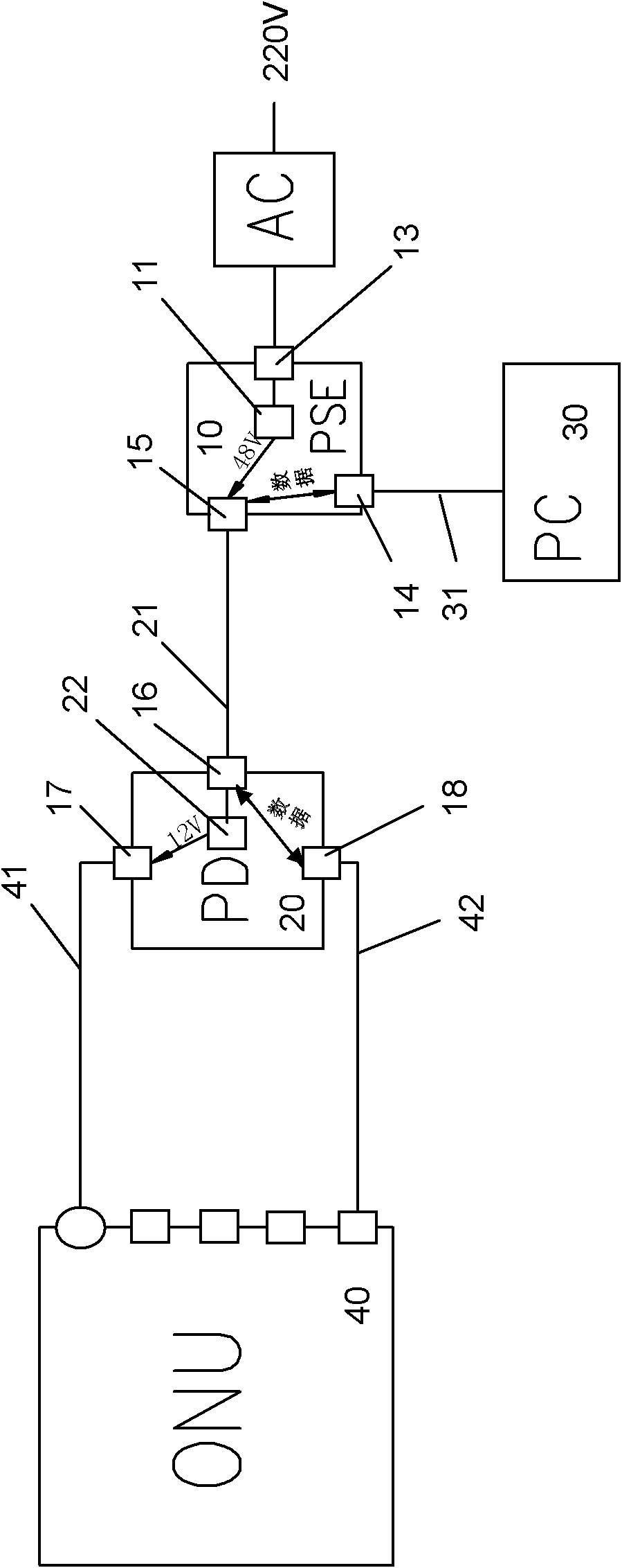
[0041] see figure 1 , figure 1 It is a structural schematic diagram of the reverse power supply device of the present invention. As shown in the figure, the reverse power supply device is connected to an active optical network unit (ONU) 40 that does not have a power-over-Ethernet function and a home terminal that does not have a power-over-Ethernet function Between equipment (PC) 30, its structure is:

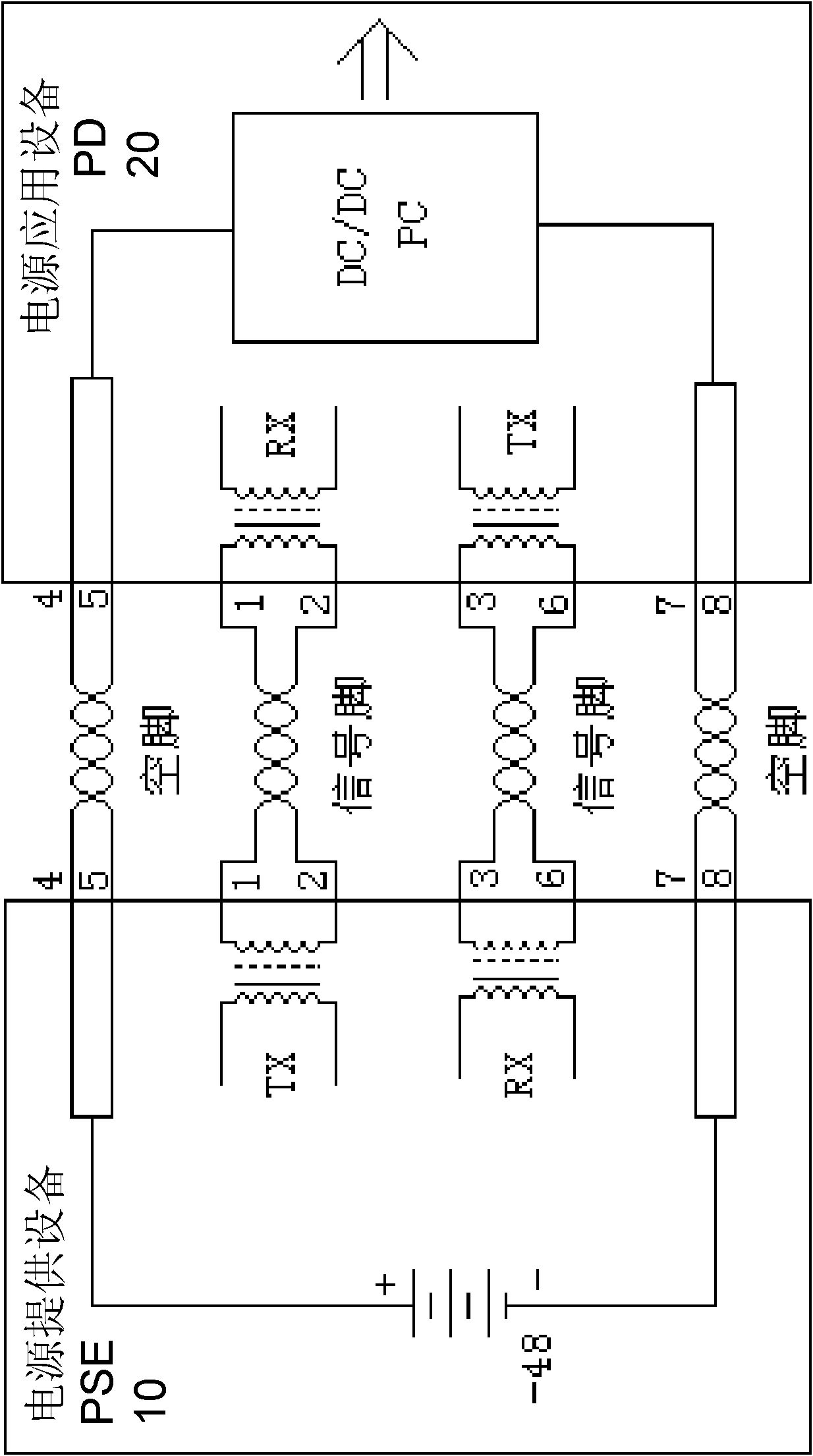
[0042] Power supply equipment (PSE) 10 is used for power management, including: power input interface 13, and it is connected with alternating current (AC) 220V power supply; , do not describe its structure in detail), its input terminal is connected with the power input interface 13, the alternating current (AC) 220V power supply of input is converted into direct current (DC) 48V and output through its outp...


PUM


Abstract

The invention relates to a reverse power supply method and a reverse power supply device aiming at passive optical network equipment and belongs to a reverse power supply device. The method and the device solve the problem that active optical network (AON) unit equipment in an AON network does not have a power supply for supplying electricity. The reverse power supply device is connected between family terminal equipment and an AON unit without an Ethernet power supply function and comprises power supply providing equipment and power supply application equipment, wherein the power supply providing equipment provides direct current 48V power supply and family terminal equipment data, the power supply and the data are reused on one Ethernet cable, and the power supply application equipment is connected with the other end of the Ethernet cable, provides direct current 12V power supply and data, and realizes the power supply and data transmission on the AON unit respectively through a power supply cable and the data Ethernet cable. The method and the device provided by the invention have the advantages that the additional pavement of new power wires or other circuits is not needed, the investment is saved, the construction period is reduced, in addition, the current and the data are transmitted through different network cable pairs, the mutual interference avoidance is ensured, and the cost of paving the power wires in outdoor places or corridors is saved.

Description

technical field [0001] The invention belongs to a reverse power supply device, in particular to a reverse power supply method and device for passive optical network equipment. Background technique [0002] Optical fiber access network (hereinafter referred to as OAN) is an access network using optical fiber transmission technology, that is, a communication system that uses optical fiber transmission in whole or in part between the local exchange office and users. Optical fiber access network can be divided into passive optical network (hereinafter referred to as PON) and active optical network (hereinafter referred to as AON), among which PON develops faster. [0003] PON means that ODN (Optical Distribution Network) does not contain any electronic devices and electronic power sources. ODN is composed of passive devices such as optical splitters (Splitter), and does not require expensive active electronic equipment. Due to the current development characteristics of OAN, man...

Claims


Application Information

Patent Timeline
Patent Type & Authority Applications(China)
IPC IPC(8): H04B10/00H04L12/10H04B10/80
Inventor 陈海龙
Owner 上海宽岱电讯科技发展有限公司
Learn More