
Load detection device mounting structure

A detection device and load technology, used in transportation and packaging, special positions of vehicles, stools, etc., can solve problems such as disconnection, bending and deformation of signal lines, and achieve the effect of suppressing disconnection or damage.

Active Publication Date: 2012-08-29
AISIN SEIKI KK
View PDF6 Cites 2 Cited by
  • Summary
  • Abstract
  • Description
  • Claims
  • Application Information

AI Technical Summary

Problems solved by technology

In addition, the signal line may be partially bent and deformed by the reaction force, and stress may be generated in the deformed part until the line is broken.

Method used


Image

  • Load detection device mounting structure
  • Load detection device mounting structure
  • Load detection device mounting structure

Examples


Embodiment Construction

[0034] Hereinafter, a first embodiment in which the mounting structure of the seating detection device for a vehicle seat according to the present invention is applied to a vehicle seat will be described with reference to the drawings. However, the directions of "front and rear, left and right, and up and down" used in this specification are all described based on the vehicle.

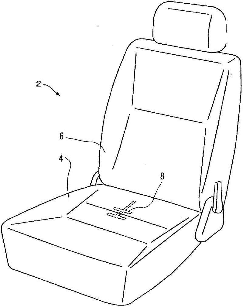
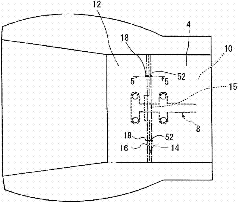
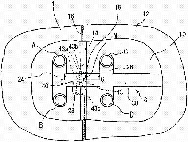
[0035] Such as figure 1 As shown, the vehicle seat 2 includes a seat cushion portion 4 , a film-shaped load detection device 8 , and a seat back portion 6 . Such as figure 2 , image 3 As shown, the seat cushion portion 4 is provided with: a cushion member 10, which is made of polyurethane or the like; The way the surface is mounted. Such as image 3 As shown, a part of the upper surface of the cushion member 10 of the seat cushion portion 4 is recessed to form a groove along the left-right direction ( image 3 The groove 14 extending in the up and down direction).

[0036] The load detection d...


PUM


Abstract

Disclosed is a load detection device mounting structure wherein wire breakage is prevented. This load detection device mounting structure is such that a film-like load detecting device is provided with detection sections which abut the seating surface of a pad member, an external output section which outputs signals, conduction sections which establish conduction between the detection sections and between the detection sections and the external output section, that bend-formed sections are formed by bending the conduction sections between a surface skin member and the seating surface of the pad member, which comprises a recessed groove, that said bend-formed sections are inserted into said recessed groove, and that thus said film-like load detecting device is disposed in such a way as to cross the recessed groove, that sliding contact sections with which the backsides of the bend-formed sections come into sliding contact are provided on the inner side surfaces of the recessed groove, that through holes are drilled from the recessed groove at those places in the pad member where the bend-formed sections are inserted, and that when the pad member undergoes compressive deformation due to a seating load, then on account of sliding between the bend-formed sections and the sliding contact sections, the bend-formed sections are permitted to move freely in the vertical direction in the through holes.

Description

technical field [0001] The present invention relates to an attachment structure of a load detection device that is installed on a seat of a vehicle and detects a seated state of an occupant. Background technique [0002] Conventionally, in order to improve the performance of various safety devices such as seat belts and airbags mounted on automobiles, there is a technology of detecting the state of an occupant sitting on a vehicle seat and controlling these safety devices. Furthermore, there is a thin and flexible film-shaped membrane switch as such a load detection device suitable for detecting the seating state of a passenger. A seat portion and a back portion of a vehicle seat are generally constructed by covering a cushion member made of polyurethane or the like with a surface member such as cloth, vinyl artificial leather, or leather. Specifically, the skin part is pulled into a groove provided on the surface of the pad part, and the pulled-in skin part is fixed to a p...

Claims


Application Information

Patent Timeline
Patent Type & Authority Applications(China)
IPC IPC(8): B60N2/44A47C7/62B60N2/90
CPCB60N2210/46B60N2/0033B60N2/0034A47C7/386
Inventor 宅间摄中山孝市近藤弘巳田中和也
Owner AISIN SEIKI KK
Learn More