
Method for determining height of caving zone of stope with internal-staggered layer-staggered position type roadway layout

A technology for roadway layout and determination method, applied in surface mining, earthwork drilling, underground mining, etc., can solve the problem that the selection of equipment and coal mining technology cannot be optimized, and the height of stope caving zone is difficult to accurately determine, etc. problems, to achieve the effect of optimizing equipment selection, optimizing the selection of coal mining technology, and ensuring safe production

Inactive Publication Date: 2012-09-05
CHINA UNIV OF MINING & TECH (BEIJING)
View PDF3 Cites 24 Cited by
  • Summary
  • Abstract
  • Description
  • Claims
  • Application Information

AI Technical Summary

Problems solved by technology

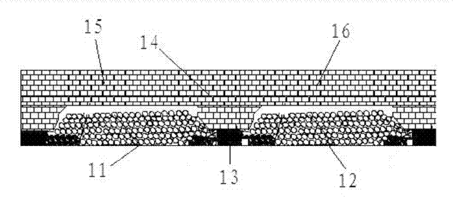
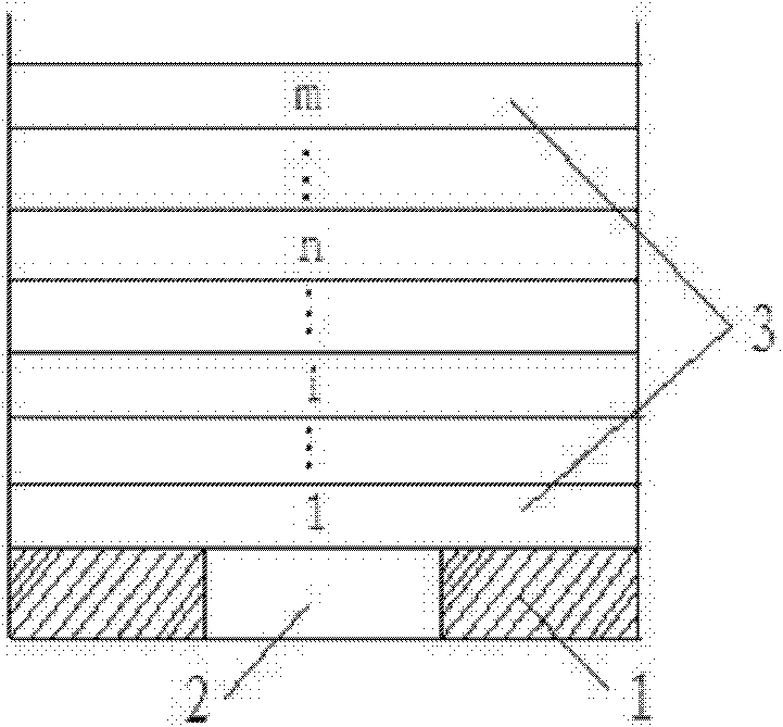
[0009] In view of this, the purpose of the present invention is to provide a method for determining the height of the caving zone in stope with staggered roadway arrangement in staggered layers, which is used to solve the problem of full-thickness coal mining when using staggered roadways in staggered layers. , due to the formation of the continuous working face, it is difficult to accurately determine the height of the stope caving zone, which makes the selection of equipment and coal mining technology unable to achieve the optimal problem

Method used


Image

  • Method for determining height of caving zone of stope with internal-staggered layer-staggered position type roadway layout
  • Method for determining height of caving zone of stope with internal-staggered layer-staggered position type roadway layout
  • Method for determining height of caving zone of stope with internal-staggered layer-staggered position type roadway layout

Examples


Embodiment Construction

[0041] The present invention will be described in detail below by taking the practical application of the method of the present invention in coal production as an example. However, those skilled in the art should realize that the present invention is not limited thereby.

[0042]The key layer in the mined rock mass has the following characteristics: geometric characteristics, compared with other same rock formations, it is thicker; lithological characteristics, compared with other rock formations, it is harder, that is, the elastic modulus is larger and the strength is higher; Deformation feature, when the key layer sinks and deforms, the subsidence of all or part of the upper rock layer is synchronized and coordinated; breaking feature, the breaking of the key layer will lead to the breaking of all or part of the upper rock layer, thereby causing a large range of rock layer movement ;Supporting characteristics, before the key layer is damaged, the form of "slab" or "beam" str...


PUM


Abstract

The invention relates to a method for determining height of a caving zone of a stope with an internal-staggered layer-staggered position type roadway layout, and the method is used for solving the problem that in a full-thickness coal mining method which uses the internal-staggered layer-staggered position type roadway layout, as a continuous working face is formed, the height of the caving zone of the stope is difficult to accurately determine, the type selection of equipment and the selection of a coal mining process cannot be optimal, and then, the safe mining is affected. According to the method for determining the height of the caving zone of the stope with the internal-staggered layer-staggered position type roadway layout, provided by the invention, a key layer is determined to be an object of study; and furthermore, according to the characteristics of the full-thickness coal mining method with the internal-staggered layer-staggered position type roadway layout, a plurality of working faces of the stope form an overlapped structure, the stope space on the working faces forming the overlapped structure are taken as a whole stope space, the key layer is judged according to the length of the whole stope space, and then, the height of the caving zone of an overlying rock layer of the mining work face is finally determined, so that the type selection of the equipment and the selection of the coal mining process are optimized, and the safe production is guaranteed.

Description

technical field [0001] The invention relates to the field of coal mining, in particular to a method for determining a stope caving zone after a continuous working face is formed when a thick coal seam adopting a staggered roadway layout in a staggered position is mined to a full height before coal mining. Background technique [0002] As we all know, due to the difference in layering characteristics of coal-measure strata, each rock layer plays a different role in rock mass activity. Some relatively hard and thick rock formations play a controlling role in the activities, that is, they play the role of bearing the main body and skeleton; some relatively weak thin rock formations only play a loading role during the activities, and most of their own weight is borne by the hard and thick rock formations. Therefore, the rock formations that mainly control the rock mass movement are called key layers, and the rock layers that only play a loading role are called follower layers. ...

Claims


Application Information

Patent Timeline
IPC IPC(8): E21C41/16
Inventor 王志强赵景礼李成武
Owner CHINA UNIV OF MINING & TECH (BEIJING)
Learn More