
Transflective mode conversion method and liquid crystal display panel

A liquid crystal display panel and liquid crystal layer technology, which is applied in nonlinear optics, instruments, optics, etc., can solve the problems of low aperture ratio, low transmittance and reflectivity, and low utilization rate of light efficiency of transflective liquid crystal displays.

Active Publication Date: 2015-02-18
BOE TECH GRP CO LTD
View PDF4 Cites 0 Cited by
  • Summary
  • Abstract
  • Description
  • Claims
  • Application Information

AI Technical Summary

Problems solved by technology

Since each pixel is divided into two sub-pixels, the transflective liquid crystal display has a low aperture ratio, low light efficiency utilization, and low transmittance and reflectivity.

Method used


Image

  • Transflective mode conversion method and liquid crystal display panel
  • Transflective mode conversion method and liquid crystal display panel
  • Transflective mode conversion method and liquid crystal display panel

Examples


Embodiment Construction

[0021] The following will clearly and completely describe the technical solutions in the embodiments of the present invention with reference to the accompanying drawings in the embodiments of the present invention. Obviously, the described embodiments are only some, not all, embodiments of the present invention. Based on the embodiments of the present invention, all other embodiments obtained by persons of ordinary skill in the art without making creative efforts belong to the protection scope of the present invention.

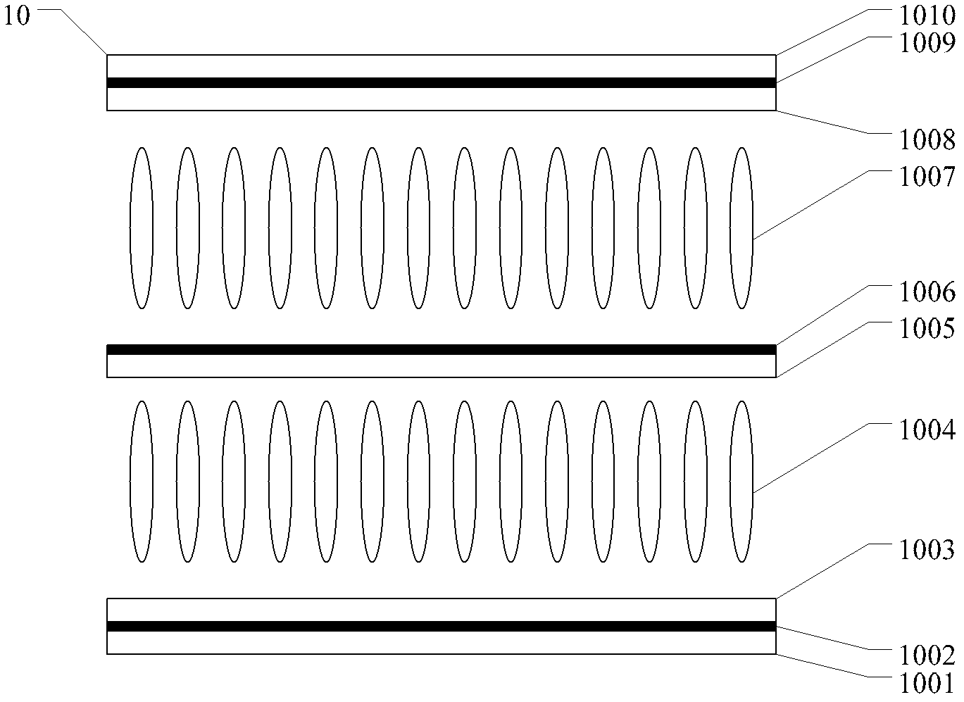
[0022] The liquid crystal display panel 10 provided by the embodiment of the present invention, such as figure 1 shown, including:

[0023] The lower polarizer 1001 is used to change the incident natural light into linearly polarized light;

[0024] The first electrode 1002 located above the lower polarizer 1001 and in contact with the lower polarizer 1001 is used to generate an electric field;

[0025] The first substrate 1003 located above the first electr...


PUM


Abstract

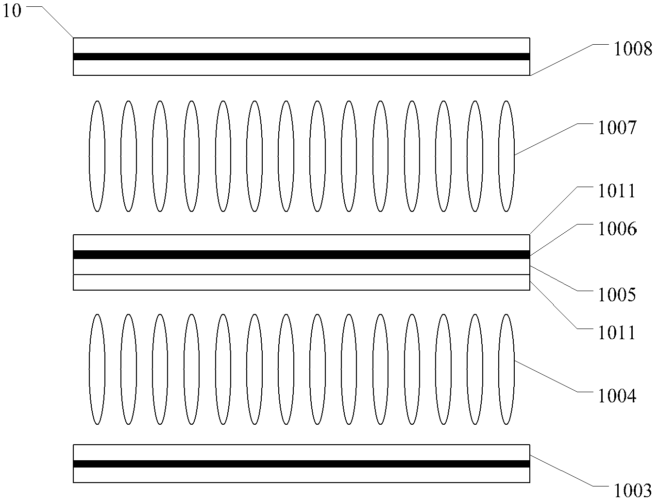
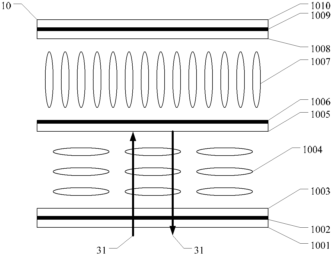
A liquid crystal display panel and a transmission / reflection mode conversion method thereof, and a display device. The liquid crystal display panel comprises: an upper polarizing piece (1010) and a lower polarizing piece (1001), the absorption axes of the upper polarizing piece (1010) and the lower polarizing piece (1001) being perpendicular to each other; and a first substrate (1003) and a second substrate (1008), the second substrate (1008) being below the upper polarizing piece (1010), and the first substrate (1003) being above the lower polarizing piece (1001). A reflection polarizing piece (1005) is disposed between the first substrate (1003) and the second substrate (1008). The reflection polarizing piece (1005) is used to reflect ambient light and transmit backlight. A first liquid crystal layer (1004) is disposed between the first substrate (1003) and the reflection polarizing piece (1005). A second liquid crystal layer (1007) is disposed between the reflection polarizing piece (1005) and the second substrate (1008). A first electrode (1002) is disposed between the lower polarizing piece (1010) and the first substrate (1003). A second electrode (1006) is disposed above the reflection polarizing piece (1005) or below the reflection polarizing piece (1005). A third electrode (1009) is disposed between the second substrate (1008) and the upper polarizing piece (1010). The first electrode (1002), the second electrode (1006), and the third electrode (1009) are used to generate an electric field and change the phase delay of the first liquid crystal layer (1004) and the second liquid crystal layer (1007).

Description

technical field [0001] The invention relates to the field of liquid crystal display manufacture, in particular to a transflective mode conversion method and a liquid crystal display panel. Background technique [0002] With the wide application of portable and outdoor information terminal electronic equipment, transflective liquid crystal display devices have been favored by people. The transflective liquid crystal display device has the characteristics of both transmissive and reflective displays, and has good visibility in a dark environment and also has good visibility outdoors under strong sunlight. [0003] Traditional transflective LCD panels divide each pixel into two sub-pixels: a transmissive area and a reflective area. The transmission area works in the dark environment in the transmission mode, and the reflection area works in the outdoors in the reflection mode. Since each pixel is divided into two sub-pixels, the transflective liquid crystal display has a low ...

Claims


Application Information

Patent Timeline
Patent Type & Authority Patents(China)
IPC IPC(8): G02F1/1335G02F1/13363G02F1/1343
CPCG02F2001/13478G02F1/1347G02F1/13478
Inventor 李会田正牧崔贤植
Owner BOE TECH GRP CO LTD
Learn More