High-voltage conductor end ground clamp

A technology for grounding clips and high-voltage wires, which is used in conductive connections, connections, and electrical component connections. Effect

Inactive Publication Date: 2012-09-05
ELECTRIC POWER RES INST OF GUANGXI POWER GRID CO LTD
View PDF4 Cites 26 Cited by
  • Summary
  • Abstract
  • Description
  • Claims
  • Application Information

AI Technical Summary

Problems solved by technology

The large-diameter wire is located at the lower part of the tongue, that is, the bottom of the eight-shaped clamp, and the wire is easy to slip
[0003] The specification of Chinese Utility Model Patent No. CN2458746Y discloses a high-voltage grounding clamp, which is composed of a clamping device and a control device. The clamping device includes a hook with a grounding wire, a tongue plate, and a tension spring. There is a groove along the hook, one end of the tongue is movably connected with the lower part of the hook, and the other end extends into the groove, the tension spring is installed on the hook, and its two ends are respectively against the hook and the tongue, and the tongue is connected The insulating pull rope of the control device, the tongue plate can be rotated by pulling the insulating pull rope. When the ground wire of this structure is used for hanging the wire, first place the hook on the wire, and then pull the insulating pull rope through the control device to make the tongue plate Rotate in the hook, under the weight of the hook or the downward force applied to the operating device, when the wire enters the bending part in the hook, and th

Method used


Image

  • High-voltage conductor end ground clamp
  • High-voltage conductor end ground clamp
  • High-voltage conductor end ground clamp

Examples


Embodiment Construction

[0015] The technical solutions of the present invention will be further described below through the accompanying drawings and embodiments.

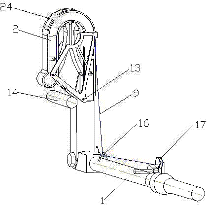
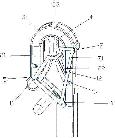
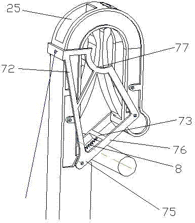
[0016] Such as figure 1 As shown, the high-voltage wire end grounding clip of the present invention includes an operating lever 1, a hook 2 with a wire grounding end, a left tongue 3, a right tongue 4, a left tension spring 5, a right tension spring 6, and a lock block 7, torsion spring 8, insulating stay cord 9, connecting pin 10, hook is made of left clamping part 21 and right clamping part 22 and the bending part 23 that connects left clamping part 21 and right clamping part 22, and bending part The top surface of 23 is provided with two symmetrically arranged left grooves 24 and right grooves 25, the lower end of the right clamping part 22 is connected with the operating rod 1, the left clamping part 21 is parallel to the right clamping part 22, The left tongue 3 and the right tongue 4 are bifurcated and arranged in the hook 2, where...


PUM


Abstract

The invention relates to a high-voltage conductor end ground clamp, comprising a hook with a ground conductor end, wherein the hook is internally and respectively connected with two rotatable tongue sheets, the two tongue sheets are oppositely arranged to form a splayed clamping opening for clamping a conductor, the hook is further provided with a locking block which is rotatably connected with the hook through a connection pin shaft; the locking block consists of two locking plates, a connection rib and a limiting plate; the two locking plates are respectively arranged at the front and the back of the hook, the connection rib is connected with the two locking plates, and the limiting plate is connected with the hook and then is adhered on the side surface of the hook; the connection pin shaft is internally sleeved with an inner side surface, a torsion spring and an insulating pull rope; the two ends of the inner side surface respectively prop against the hook, the torsion spring is arranged on the connection rib of the locking block, the insulating pull rope is fixed on the locking block and is used for pulling the locking block to rotate, the side edge of the lower part of each locking plate is provided with an inclined line conveniently guiding the conductor into the hook, the edge of the upper part of each locking plate is provided with an arc clamping opening matched with the conductor, the arc clamping opening is used for clamping double tongue sheets, and the conductor is clamped so as to prevent the conductor from moving downwards and to be fixed completely; and under a high wind environment, the conductor generates wave and can be prevented from withdrawing from a clamp.

Description

technical field [0001] The invention relates to a high-voltage wire end grounding clamp, in particular to a wire end grounding clamp which can be applied to a 500kV tension tower. technical background [0002] The grounding clamp at the wire end is a safety tool for temporarily short-circuiting grounding of the equipment that has been powered off. Hazards, while releasing the remaining charge of the power-off equipment. At present, the wire clamps used by various power grid companies mainly include double spring type, single spring type, flat spiral type and throat type, etc. Among them, the double spring type is widely used because the clamping force generated when clamping the wire is relatively balanced, and it is easier to operate. In use, its main structure consists of a hook, two tongues, an operating rod, and two tension springs. The operating rod is connected to the hook. The hook has two clamping parts and a curved part connecting the clamping parts. The two tongue...

Claims


Application Information

Patent Timeline
IPC IPC(8): H01R11/14H01R4/48
Inventor 许飞王凯李岩舟陈渊龙慧谢奇师汪丽川周柯蒋学军徐波滕辉
Owner ELECTRIC POWER RES INST OF GUANGXI POWER GRID CO LTD
Why Eureka
Try Eureka