

Cutting bed
A cutting bed and cutting technology, which is applied in the field of cutting bed, can solve the problems such as the inability to satisfy the long-distance rapid movement and accurate positioning of the cutting head, the inability to overcome the subtle non-parallel conditions of the guide rails, and the unsmooth movement of the beam, etc., to achieve splicing and The overall leveling is convenient, the overall rigidity is fastened, and the structure is stable and reliable.
- Summary
- Abstract
- Description
- Claims
- Application Information
AI Technical Summary
Problems solved by technology
Method used
Image

Examples
Embodiment 1
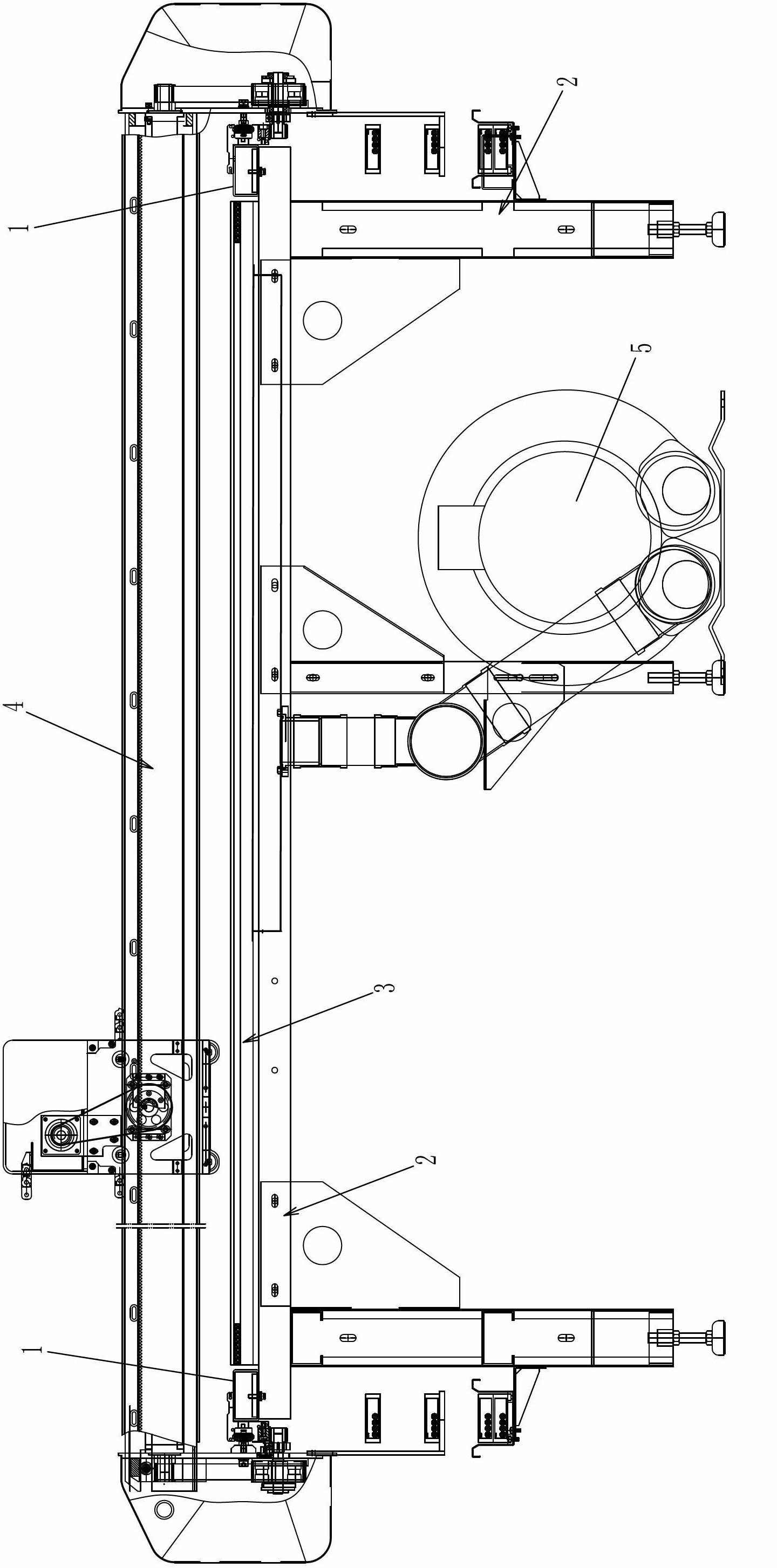
[0057] Such as figure 1 A cutting bed shown includes a frame 2 , a vacuum suction device 3 and a cutting head moving mechanism 4 .
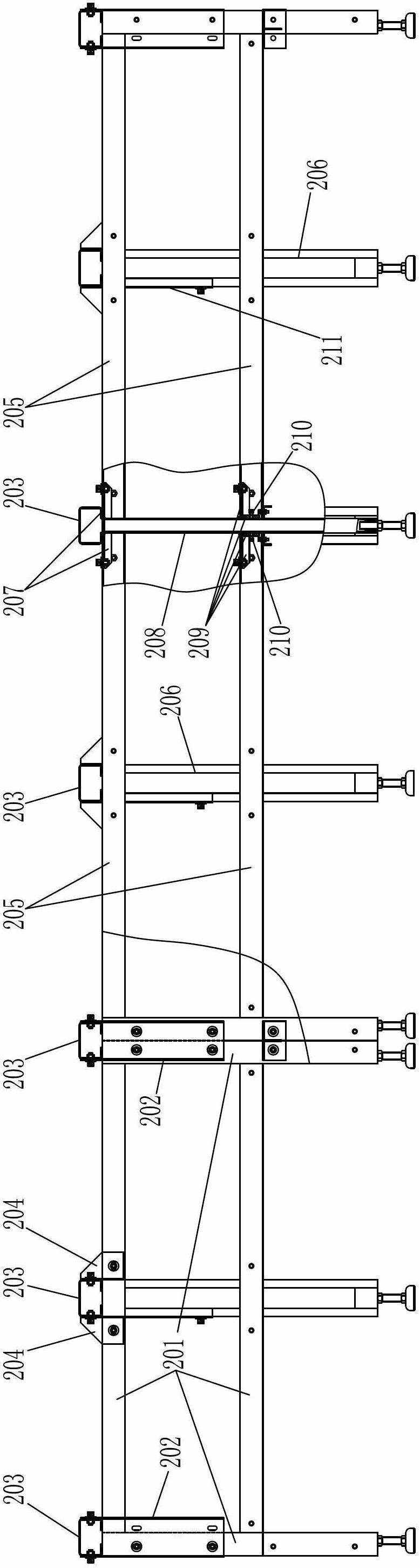
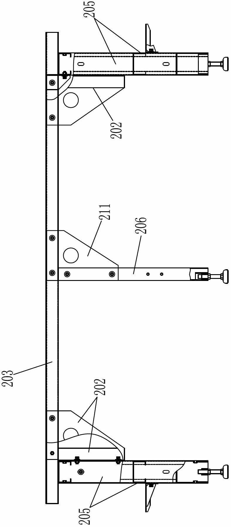
[0058] Such as figure 2 , image 3 , Figure 4 As shown, the rack 2 includes a first row of support body assemblies, a second row of support body assemblies and a plurality of crossbar assemblies, and the first row of support body assemblies and the second row of support body assemblies are formed by connecting a plurality of support bodies side by side , the first row of support body assemblies and the second row of support body assemblies are placed in parallel and connected as a whole through the plurality of cross bar assemblies, and the plurality of cross bar assemblies are arranged in parallel with each other and connected with the first row of support body assemblies , the second row of support body components are vertical; where, such as Figure 7 As shown, the cross bar assembly includes a cross bar 203 and at least one middle leg 2...
PUM
 Abstract
Description
Claims
Application Information