
Corner protector structure of cylindrical mold reinforcing device

A reinforcement device and corner protection technology, which is applied to building construction, formwork/formwork/work frame, and on-site preparation of building components, can solve the problems of large loss, waste, and complicated operation of sawn wood

Inactive Publication Date: 2012-09-12
曹健厂
View PDF8 Cites 1 Cited by
  • Summary
  • Abstract
  • Description
  • Claims
  • Application Information

AI Technical Summary

Problems solved by technology

[0005] With this method of reinforcement, more square wood, steel nails, steel pipes, and iron wires are used. Saw steel pipes and sawn square wood are more wasted and wasteful. Too much steel nails will directly nail the column formwork and shorten the column formwork. The number of turnovers; this reinforcement method is relatively complicated to operate, and the reinforcement, disassembly, and installation quality inspection of the cylindrical formwork are all labor-intensive, resulting in high costs and slow progress
Due to the sunlight and rain in the process of using the square wood, it is easy to deform and deteriorate, and the operation of the reinforcement method is complicated, and the workers are prone to mistakes and omissions in the operation. Defective phenomena affecting quality such as pockmarked surface and honeycomb

Method used


Image

  • Corner protector structure of cylindrical mold reinforcing device
  • Corner protector structure of cylindrical mold reinforcing device
  • Corner protector structure of cylindrical mold reinforcing device

Examples


Embodiment Construction

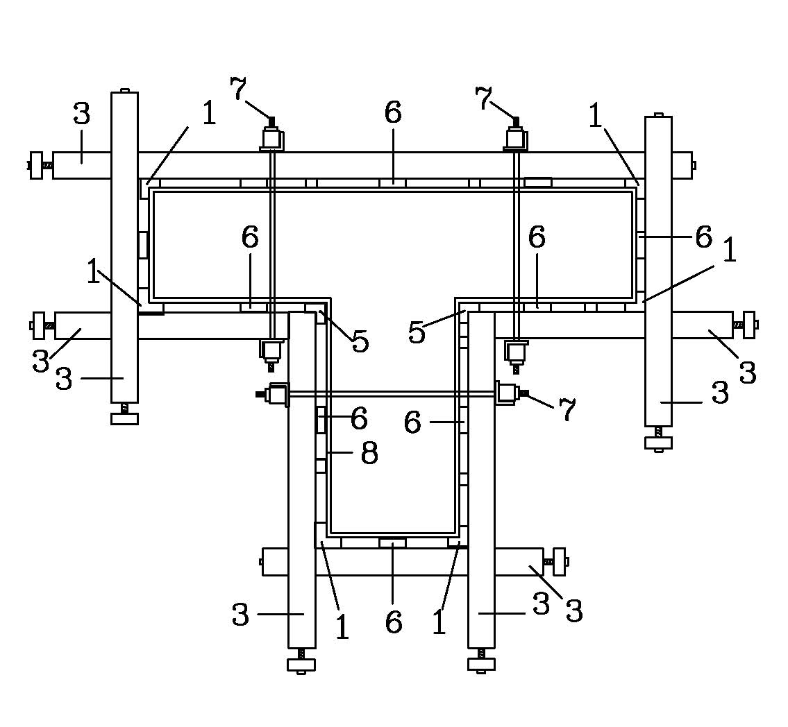
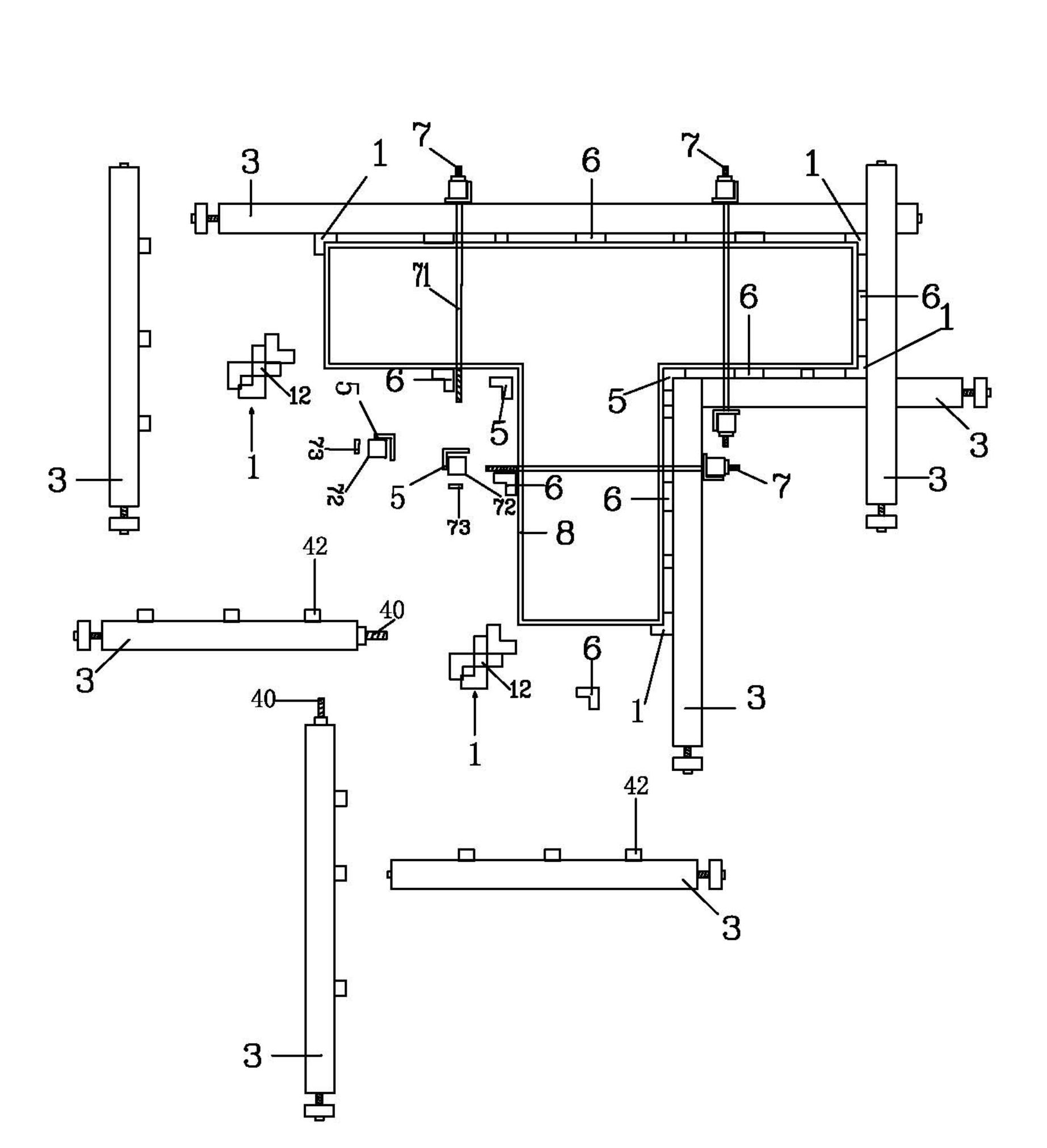
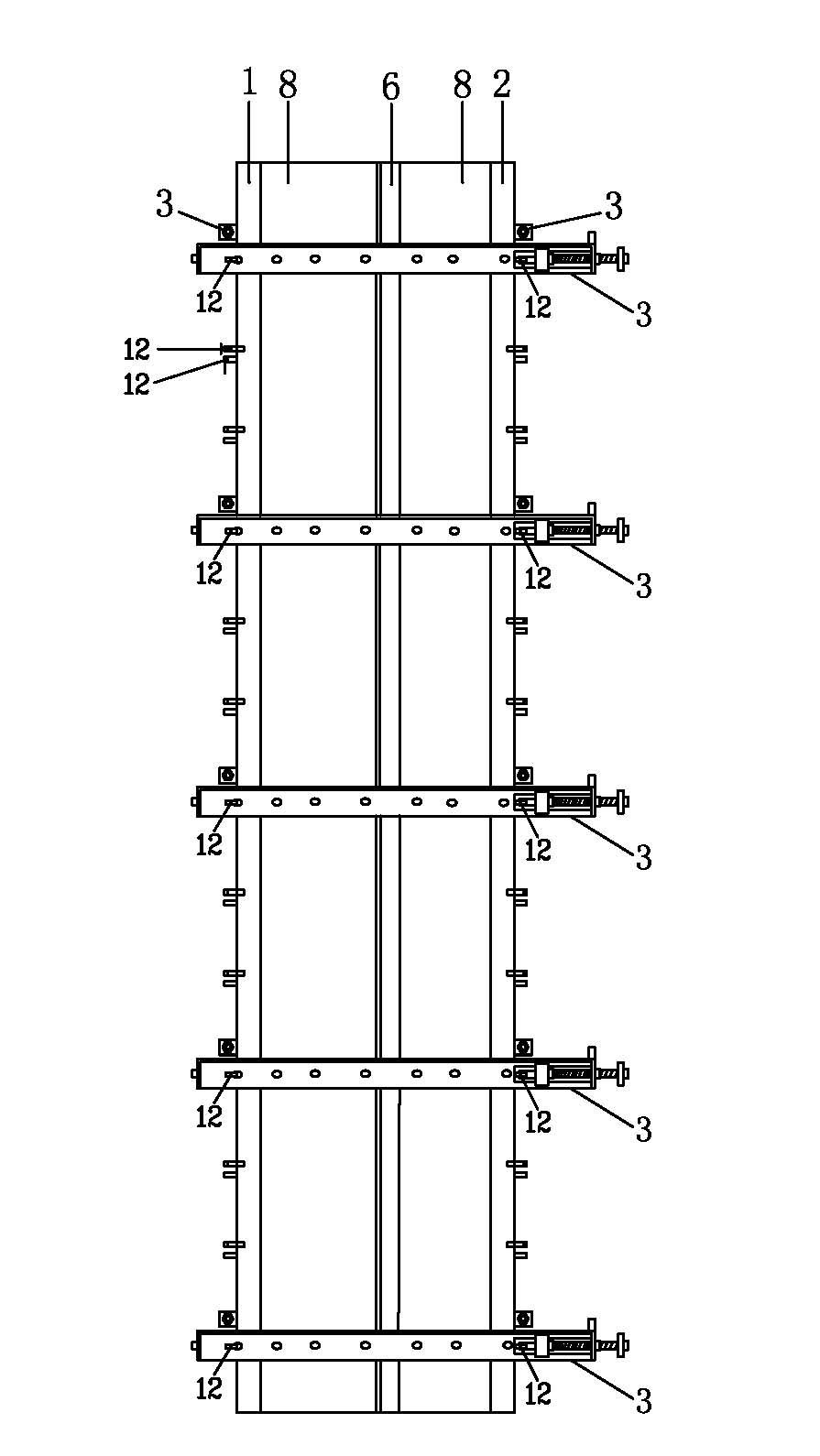
[0027] Such as Figure 1 to Figure 11 As shown, the present invention provides a groove buckle structure of a reinforcing device of a cylindrical mold, which mainly includes several male corner corner protectors 1, which respectively enclose the male corners of the cylindrical mold 8 longitudinally (not shown in the figure) several female corner corner protectors 5, which longitudinally enclose the female corners of the cylindrical mold 8 respectively (not shown in the figure); several pressing plate encryption parts 6, said pressing plate encryption parts 6 are longitudinally fixed on the cylindrical mold 8 and Between the karaoke rods 3, the several karaoke rods 3 mentioned above are staggered in pairs to surround the male corner corner protector 1, the female corner corner protector 5, the pressure plate encryption member 6, and the combination groove buckle screw rod 7 1. Form enveloping reinforcement to the cylindrical mold 8 . A plurality of groove buckles 72 and screw ...


PUM


Abstract

The invention provides a corner protector structure of a cylindrical mold reinforcing device. The reinforcing device mainly comprises a plurality of clamping draw bars, a plurality of pressure plate sealing parts, a plurality of grooved fastener and screw combinations, a plurality of external corner protectors and a plurality of internal corner protectors, wherein the external corner protectors respectively longitudinally wrap external corners of a cylindrical mold, four positioning pin holes are respectively longitudinally disposed on two side surfaces of each external corner protector, fixing hooks are longitudinally disposed on two sides of each external corner protector and used for being transversely connected with the corresponding clamping draw bars, service distances of the clamping draw bars are adjusted by the hooks, and fixed convex connecting ports which can be conveniently connected with a higher work face are arranged at ends of the external corner protectors; and the internal corner protectors respectively longitudinally wrap internal corners of the cylindrical mold, four positioning pin holes are respectively longitudinally arranged on two side surfaces of each internal corner protector, screw holes which are uniformly distributed are longitudinally arranged on one side surface of each internal corner protector, and the internal corner protectors and the grooved fastener and screw combinations are longitudinally pressed on the outer sides of the clamping draw bars after being combined. The cylindrical mold is reinforced by the corner protectors, probability of slurry leakage and mold expansion of the corners of the cylindrical mold is reduced, the corner protector structure is operated simply and conveniently, and assembling speed and disassembling speed of the cylindrical mold are increased.

Description

technical field [0001] The invention relates to a cylindrical mold reinforcement device, in particular to a corner protector structure of the cylindrical mold reinforcement device which prevents the cylindrical mold from expanding and bursting due to pouring fillers. Background technique [0002] At present, the cast-in-place concrete column formwork in the construction industry is generally reinforced by materials such as plywood, square wood, steel nails, steel pipes, iron wires, screws, and column clamps. [0003] The general reinforcement method is to first nail the formwork to form a column formwork during installation, then nail dense nails at the corners of the formwork and combine iron wires to reinforce the corners to prevent grout leakage and form expansion, and then nail on the side of the square wood. Fix the square wood on the column formwork, and then tighten the pressure plate to fix it, then bind the steel pipe of the saw section with iron wires, combine the ...

Claims


Application Information

Patent Timeline
IPC IPC(8): E04G13/02
Inventor 曹健厂
Owner 曹健厂
Learn More