Humanoid robot leg mechanism

A humanoid robot and leg mechanism technology, applied in the field of robotics, can solve problems such as difficult installation, poor structural strength, and heavy weight, and achieve the goals of reducing overall weight and installation errors, reducing the number of uses, and improving processing efficiency and installation speed Effect

Pending Publication Date: 2018-05-04
BEIJING GANGTIEXIA TECH CO LTD
View PDF0 Cites 10 Cited by
  • Summary
  • Abstract
  • Description
  • Claims
  • Application Information

AI Technical Summary

Problems solved by technology

[0004] The purpose of the present invention is to provide a humanoid robot leg mechanism to solve the problems o

Method used


Image

  • Humanoid robot leg mechanism
  • Humanoid robot leg mechanism
  • Humanoid robot leg mechanism

Examples


Example Embodiment

[0025] Example 1

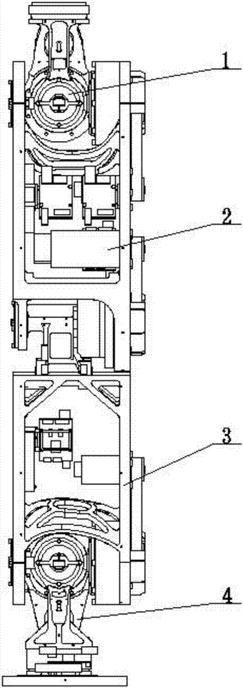
[0026] The humanoid robot leg mechanism of this embodiment 1 includes a thigh mechanism 2, a hip joint mechanism 1 is threadedly connected to the upper end of the thigh mechanism 2, and a calf mechanism 3 is threaded to the lower end of the thigh mechanism 2. The lower end of the lower leg mechanism 3 is connected with an ankle joint and a sole mechanism 4 by bolts.

[0027] The hip joint mechanism 1 has two degrees of freedom in YAW and ROLL directions; the thigh mechanism 2 has two degrees of freedom in the upper and lower PITCH directions; the calf mechanism 3 has one degree of freedom in the PITCH direction; The mechanism 4 has one degree of freedom in the ROLL direction; the leg mechanism of the humanoid robot of the present invention can complete the humanoid walking gait movement through the combination of the above six degrees of freedom.

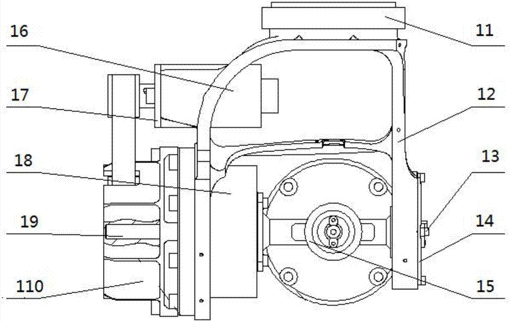
[0028] The hip joint mechanism 1 includes a hip joint U-shaped piece 12, a first harmonic reducer 11 is fixed ...

Example Embodiment

[0030] Example 2

[0031] Further, embodiment 2 adds the following features and connection relations on the basis of embodiment 1:

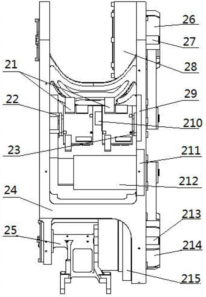
[0032]The thigh mechanism 2 includes a thigh main part 24, a second speed reducer end cover 26 and a third harmonic speed reducer 28 are fixed on the upper part of the thigh main part 24 by bolts, and on one side of the thigh main part 24 A first circuit board support 22 is threaded on the baffle, and a second circuit board support 23 is threaded on the baffle on the other side of the thigh main part 24. The first circuit board support 22 and the second circuit board support Both circuit board brackets 23 are fixed with a motor drive circuit board 21 by bolts, and a second speed reducer shaft 27 is fixed by bolts along the axial direction of the third harmonic speed reducer 28 at its end. The other end of the speed reducer shaft 27 extends into the bearing arranged on the second speed reducer end cover 26, and the first thigh driving motor 210 i...

Example Embodiment

[0035] Example 3

[0036] Further, embodiment 3 adds the following features and connection relations on the basis of embodiment 2:

[0037] The shank mechanism 3 includes a shank main part 31 on which a shank driving motor 32 is fixed by bolts. In Embodiment 3, one degree of freedom can be realized through the lower leg drive motor 32 .

[0038] The ankle joint and sole mechanism 4 includes a sole plate 45, a torque sensor 43 and a third circuit board support 44 are fixed on the upper end of the sole plate 45 by bolts, and an ankle joint is fixed on the upper end of the torque sensor 43 by bolts. U-shaped piece 42, a first bearing end cover 411 is threadedly connected to one side of the upper part of the ankle joint U-shaped piece 42, and a second encoder 41 is fixed on the outer wall of the first bearing end cover 411 by bolts On the other side of the upper part of the ankle joint U-shaped part 42, a fifth harmonic reducer 410 is fixed by bolts, and one end of the fourth re...


PUM


Abstract

The invention discloses a humanoid robot leg mechanism. The mechanism comprises a thigh mechanism, a hip joint mechanism is in threaded connection with the upper end of the thigh mechanism, a shank mechanism is in threaded connection with the lower end of the thigh mechanism, and an ankle and sole mechanism is connected with the lower end of the shank mechanism through bolts; the hip joint mechanism has degrees of freedom in directions of YAW and ROLL; the thigh mechanism has degrees of freedom in upper and lower directions of PITCH; the shank mechanism has one degree of freedom in the direction of PITCH; the ankle and sole mechanism has one degree of freedom in the direction of ROLL; human-like walking gait movements can be completed by the humanoid robot leg mechanism through the combination of six degrees of freedom. According to the humanoid robot leg mechanism, all components in the humanoid robot leg mechanism are processed to reduce weights, a large number of integrated spare parts and universal spare parts are designed, the using number of the bolts, overall weight and installation errors are reduced, and installation simplicity and strength of the spare parts are increased.

Description

technical field [0001] The invention relates to the technical field of robots, in particular to a humanoid robot leg mechanism. Background technique [0002] In the past ten years, biped humanoid robots have gradually become a research hotspot at home and abroad, and the walking of biped humanoid robots is the focus of research. In order to make the biped robot walk more stably, it is necessary to reduce the weight of the legs to the greatest extent to improve the position of the center of mass of the robot. Most of the legs of the existing biped humanoid robot are composed of a large number of parts, resulting in heavy weight of the legs, difficulty in installation, poor installation accuracy and poor structural strength. In addition, the number of degrees of freedom of the traditional humanoid robot leg mechanism is small, and it cannot complete more actions, which limits the scope of use of the robot. [0003] Therefore, it is necessary to design a humanoid robot leg me...

Claims


Application Information

Patent Timeline
IPC IPC(8): B62D57/032
CPCB62D57/032
Inventor 苑全旺陈玉娟骆鹏王家俊李冰川
Owner BEIJING GANGTIEXIA TECH CO LTD
Why Eureka
Try Eureka