Method and device for driving internal combustion engine by straight shaft

A technology of internal combustion engine and direct shaft, which is applied in the direction of transmission, machine/engine, mechanical equipment, etc. It can solve the problems of wasting fuel, hindering the output torque of internal combustion engine, etc., and achieve the goal of improving output efficiency, reducing radial force and high output efficiency Effect

Inactive Publication Date: 2012-09-12
曹德新
View PDF6 Cites 13 Cited by
  • Summary
  • Abstract
  • Description
  • Claims
  • Application Information

AI Technical Summary

Problems solved by technology

[0003] Since the connecting rod and the crank rotate, the connecting rod and the plane of crank rotation form a variable included angle, and the force acting on the crank by the connecting rod is decomposed into the radial force in the radial direction of the crank and the tangential force in the tangential direction of the crank rotation circle. Only the tangential force pushes the crankshaft to rotate, thereby doing work externally, while the radial force only produces pressure and tension on the crankshaft. It not only does not perform external work, but also causes friction loss between the piston and the cylinder, which hinders the internal combustion engine. output torque, waste fuel

Method used


Image

  • Method and device for driving internal combustion engine by straight shaft
  • Method and device for driving internal combustion engine by straight shaft
  • Method and device for driving internal combustion engine by straight shaft

Examples


Embodiment Construction

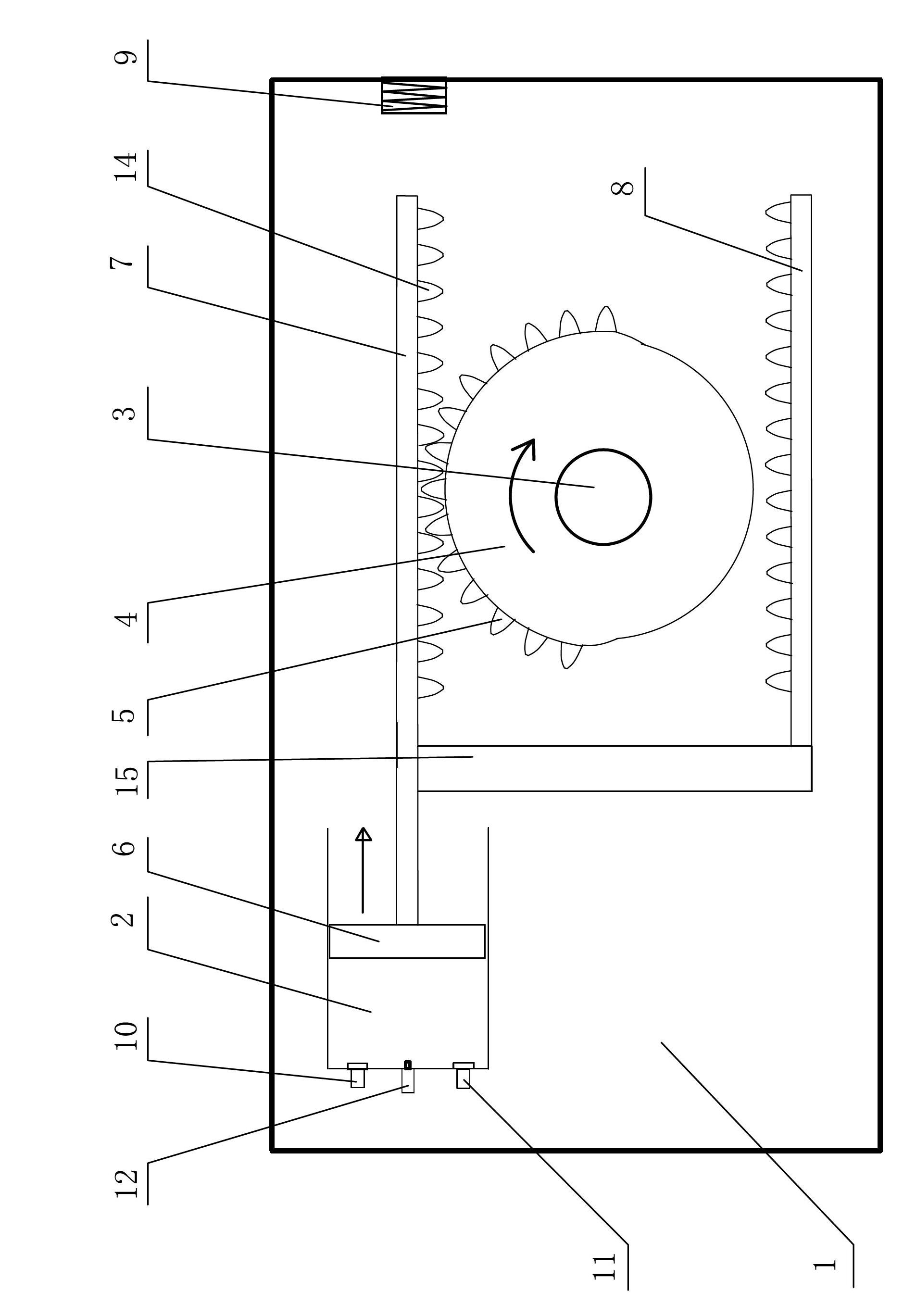
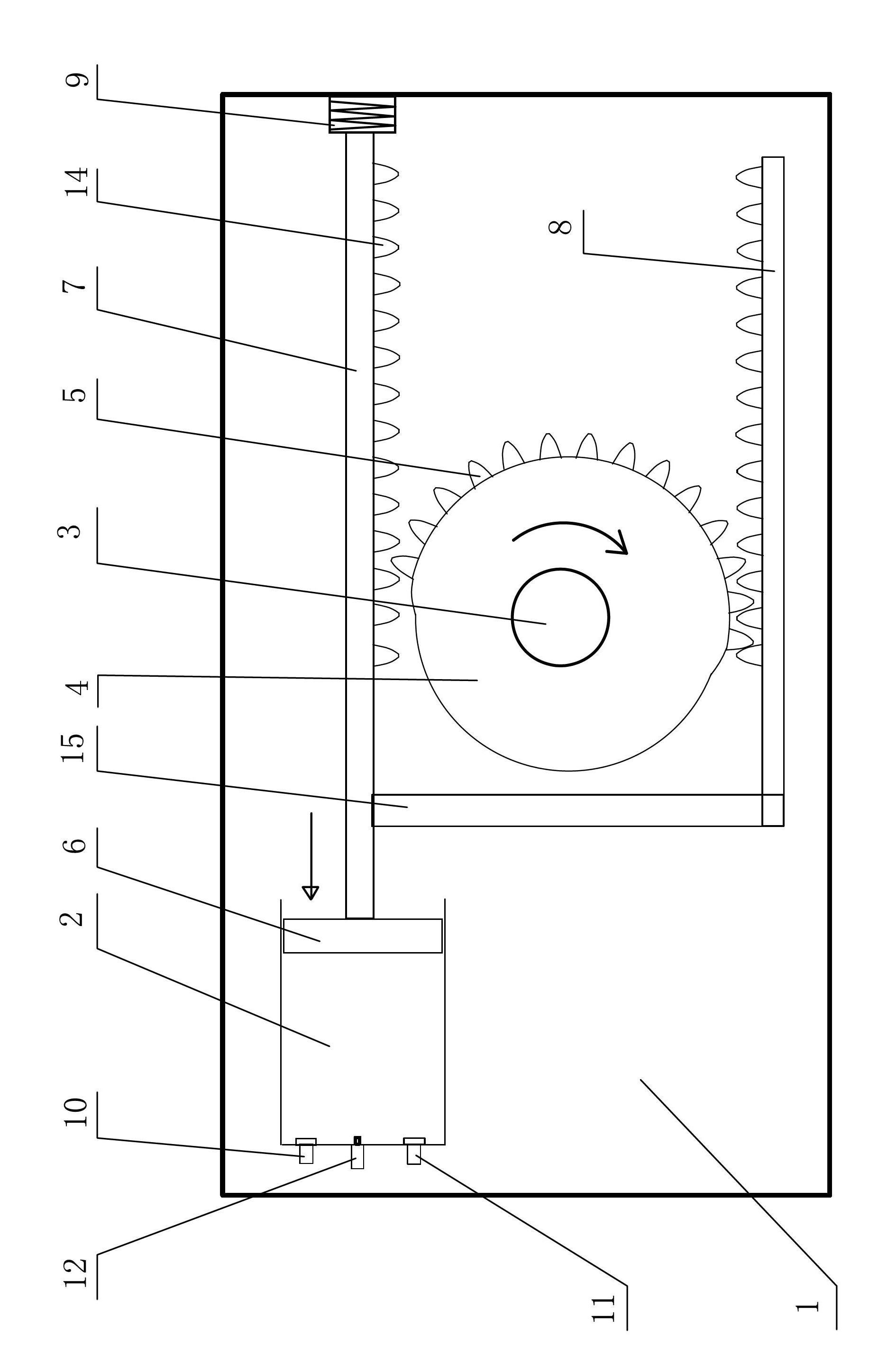
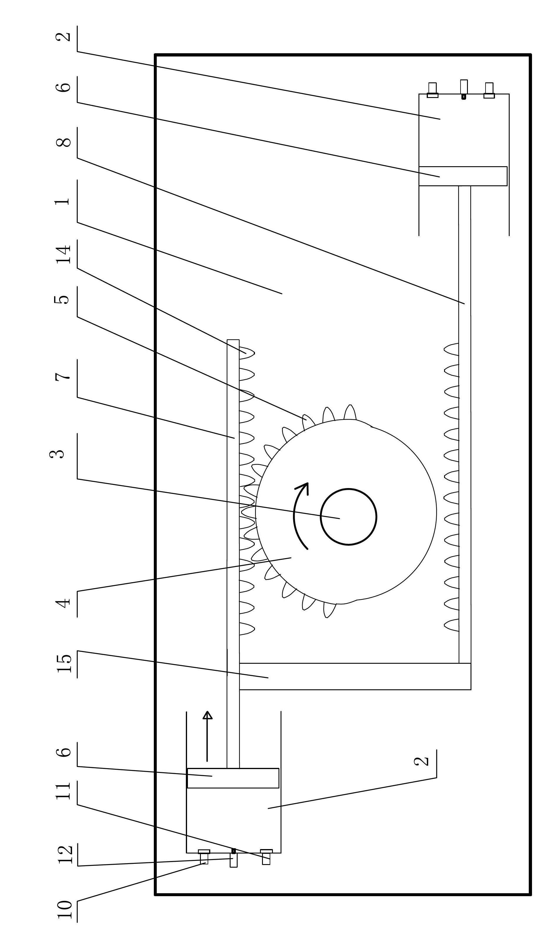
[0028] The device, method and technical solution of the present invention will be further described below in conjunction with the accompanying drawings.

[0029] The direct axis drive internal combustion engine device of the present invention is made up of connecting rod and connecting rod driving mechanism, and described connecting rod is made of parallel straight connecting rod 7 and secondary connecting rod 8, and described secondary connecting rod 8 is connected with straight connecting rod by vertical transmission rod 15 7 rod body connection (the transmission rod 15 and the secondary connecting rod 8 form an "L" shape); the connecting rod drive mechanism includes a straight shaft 3, a transmission wheel 4, a half-circular gear 5 meshing with each other, a rack 14 and a flywheel 13, so Said driving wheel 4 and flywheel 13 are coaxially installed on the straight shaft 3, and the driving wheel 4 is placed in the plane where the straight connecting rod 7 and the auxiliary con...


PUM


Abstract

The invention discloses a method and a device for driving an internal combustion engine by a straight shaft. Operating cycle of air intake, compression, do work and air exhaust is completed by the piston motion of the air cylinder driven by a straight connecting rod; the configuration direction of the straight connecting rod is consistent with the motion direction of a piston; an auxiliary connecting rod which is linked with the straight connecting rod in parallel is also arranged; the straight shaft is arranged between the straight connecting rod and the auxiliary connecting rod; a transmission wheel and a flywheel are installed on the straight shaft; the transmission wheel is positioned in the same plane with the straight connecting rod and the auxiliary connecting rod; the transmission wheel is provided with a semi-cycle gear; during the rotation process of the transmission wheel, the semi-cycle gear is alternatively meshed with gear racks on the straight connecting rod and the auxiliary connecting rod so as to generate opposite pushing to the straight connecting rod and the auxiliary connecting rod, thus the straight connecting rod and the auxiliary connecting rod perform linear reciprocating motion at the same time, and the operating cycle of the piston is realized; and by applying the technique provided by the invention, the single-cylinder driving, the dual-cylinder driving, the four-cylinder driving, the eight-cylinder driving and the twelve-cylinder driving can be realized. According to the invention, the output efficiency of the internal combustion engine can be improved by 50%-70%.

Description

(1) Technical field: [0001] The invention relates to engine technology, in particular to a direct-shaft driving internal combustion engine method and a direct shaft driving internal combustion engine device. (2) Background technology: [0002] Among the power used by automobiles and ships today, the vast majority are reciprocating piston internal combustion engines, and the fuels used are gasoline or diesel. A working cycle of a reciprocating piston internal combustion engine has four strokes and two strokes. In the power stroke, the driving process is: the fuel burns in the cylinder to generate thrust on the piston, the piston pushes the connecting rod, and the connecting rod drives the crank to rotate the crankshaft and perform work externally. ; In the intake stroke, compression stroke and exhaust stroke, the crankshaft pushes or pulls the piston through the connecting rod to complete the three strokes by utilizing the rotational inertia of the internal combustion engine'...

Claims


Application Information

Patent Timeline
Patent Type & Authority Applications(China)
IPC IPC(8): F02B75/40F02B75/18F16H37/12
Inventor 曹德新
Owner 曹德新
Why Eureka
Try Eureka