Assembly method of non-return device

An assembly method and backstop technology, applied to clutches, one-way clutches, mechanical equipment, etc., can solve the problems of reduced assembly efficiency, inability to insert, difficulties, etc., to ensure production efficiency, increase assembly speed, and high pass rate Effect

Active Publication Date: 2012-09-12
浙江鑫隆机械制造有限公司
View PDF3 Cites 1 Cited by
  • Summary
  • Abstract
  • Description
  • Claims
  • Application Information

AI Technical Summary

Problems solved by technology

[0002] The backstop is mainly composed of outer casing, arm plate, inner sleeve, side plate, roller assembly, bearing, connecting plate, end cover, outer sealing ring and inner sealing ring. At present, when assembling the backstop, the connecting plate Preheating with the bearing, put the connecting plate, bearing and inner sealing ring on the inner sleeve in sequence, and then put it into the component composed of the outer sleeve and the arm plate, and finally directly install the rolling bearing between the inner sleeve and the outer sleeve. The side plates of the subassembly, since the side plates are divided into two pieces, are punched separately when punching holes. Therefore, the errors generated during the punching will cause the corresponding holes on

Method used


Image

  • Assembly method of non-return device
  • Assembly method of non-return device
  • Assembly method of non-return device

Examples


Embodiment Construction

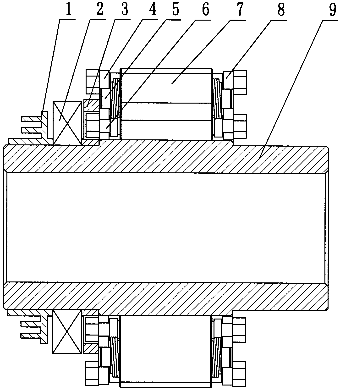
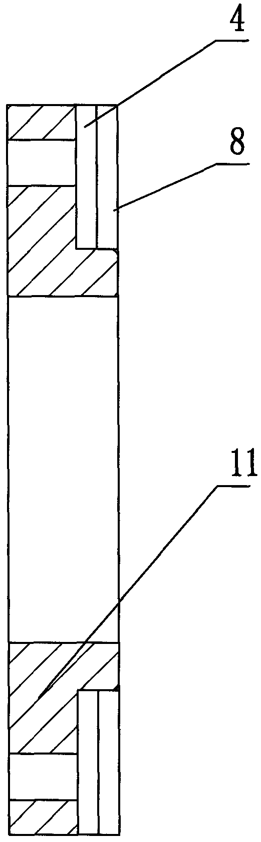
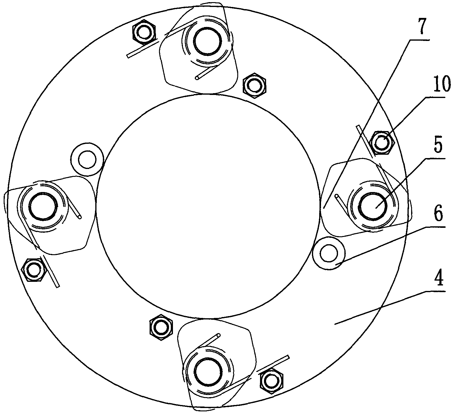
[0018] Referring to the accompanying drawings, in the assembly method of this backstop, the backstop includes two side plates 4, 8, a roller assembly, a connecting plate 3, an inner sealing ring 1, a bearing 2 and an inner sleeve 9, wherein the roller The assembly is installed between the two side plates 4, 8, the roller assembly includes a cam 7, a camshaft 5, a retaining post 6, and a stud 10, and the cam 7 is installed between the two side plates 4, 8 through the camshaft 5 , at the same time, the two side plates 4 and 8 are also connected by retaining columns 6 and studs 10. When assembling, the two side plates 4 and 8 are spot welded together earlier, put on a mold 11, and the two sides are connected by a drilling mold. The plates 4 and 8 are simultaneously drilled, and the drill holes include the retaining column installation hole, the cam installation hole and the stud hole, and the same marks are marked on the positions where the two side plates 4 and 8 are drilled simu...


PUM


Abstract

The invention discloses an assembly method of a non-return device and is characterized in that the non-return device comprises two side plates, a roller component, a connecting plate, an inner sealing ring and an inner sleeve, wherein the roller component is mounted between the two side plates, the two side plates are firstly sleeved on a mold and are welded together through spot welding, holes are drilled in the two side plates through drilling molds, and identical marks are marked on the positions of the drilled holes of the two side plates; the two side plates which are welded together are separated, the holes with the same marks on the two side plates are aligned, and the roller component is mounted between the two side plates; the two side plates with the roller component mounted therebetween are sleeved on a fixed shaft, and the flexibility of a cam in the roller component is detected; the inner sealing ring and the connecting plate are sequentially sleeved on the inner sleeve, and then the inner sleeve on which the inner sealing ring and the connecting plate are sleeved is sleeved on a part consisting of an arm plate and an outer sleeve; and finally, the roller component is sleeved between the outer sleeve and the inner sleeve, and the non-return device product is constructed. The non-return device employing the assembly method can be assembled quickly and conveniently, and the qualified rate is high.

Description

technical field [0001] The invention relates to a backstop, in particular to an assembly method of the backstop. Background technique [0002] The backstop is mainly composed of outer casing, arm plate, inner sleeve, side plate, roller assembly, bearing, connecting plate, end cover, outer sealing ring and inner sealing ring. At present, when assembling the backstop, the connecting plate Preheating with the bearing, put the connecting plate, bearing and inner sealing ring on the inner sleeve in sequence, and then put it into the component composed of the outer sleeve and the arm plate, and finally directly install the rolling bearing between the inner sleeve and the outer sleeve. The side plates of the subassembly, since the side plates are divided into two pieces, are punched separately when punching holes. Therefore, the errors generated during the punching will cause the corresponding holes on the two side plates to not be completely aligned. Install the upper roller assem...

Claims


Application Information

Patent Timeline
IPC IPC(8): F16D41/064
Inventor 邵文杰冯丰海何永松
Owner 浙江鑫隆机械制造有限公司
Why Eureka
Try Eureka