Magnetic filter for automatic transmission

A technology of automatic transmission and filter, which is applied in the direction of engine lubrication, engine components, lubricating parts, etc. It can solve the problem that the filter cannot filter small iron powder, etc., and achieve the effect of improving service life and filter performance

Inactive Publication Date: 2012-09-12
吴军红
View PDF7 Cites 7 Cited by
  • Summary
  • Abstract
  • Description
  • Claims
  • Application Information

AI Technical Summary

Problems solved by technology

[0003] The purpose of the present invention is to provide a magnetic filter for automatic transmission in o

Method used


Image

  • Magnetic filter for automatic transmission
  • Magnetic filter for automatic transmission
  • Magnetic filter for automatic transmission

Examples


Embodiment Construction

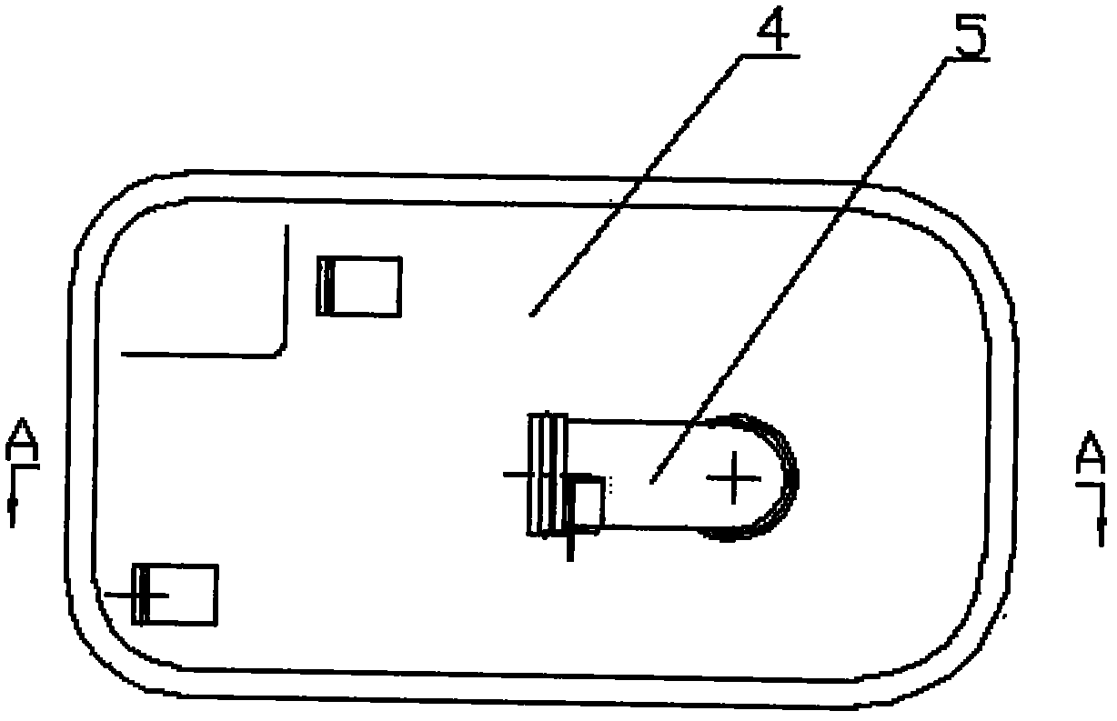
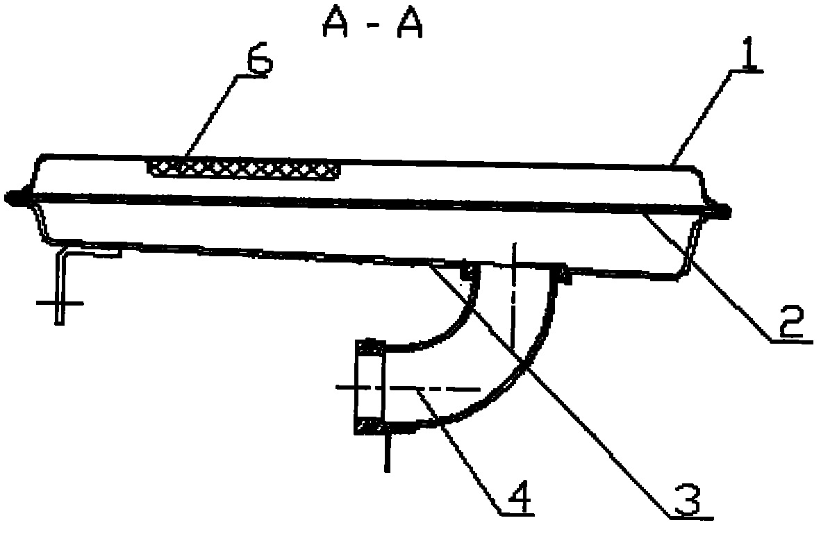
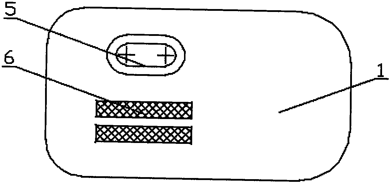
[0016] Such as figure 1 As shown, a magnetic filter for an automatic transmission of the present invention includes an upper casing 3 injection-molded from a non-metallic material, the upper casing 3 is provided with an oil outlet, and the oil outlet is located on the upper casing One side, and stretch out one end oil channel to form oil outlet pipe 4, as figure 2 As shown, the upper shell 3 and the corresponding lower shell 1 are connected by stamping and flanging, and a filter element 2 is provided at the junction of the upper and lower shells, and the filter element 2 is pressed by the upper and lower shells. tight to achieve fixation, such as image 3 As shown, the lower casing 1 is provided with an oil inlet 5, and two rectangular grooves are arranged on the side of the lower casing oil inlet near the oil outlet pipe, and each rectangular groove is provided with a corresponding permanent magnet 6 . Beneficial effects of the present invention The permanent magnet is us...


PUM


Abstract

The invention relates to a magnetic filter for an automatic transmission, comprising an upper shell (3), a lower shell (1), an oil inlet (5) and an oil outlet pipe correspondingly disposed in the shells, and a filter element (2) arranged at the joint position of the two shells. The magnetic filter is characterized in that a set of permanent magnets (6) is disposed on the lower shell. The beneficial effects of the magnetic filter for an automatic transmission are that with the permanent magnets playing a role in filter of fine iron powders, the service life of the automatic transmission is increased, and filtering performance of the filter is improved.

Description

technical field [0001] The present invention relates to a car filter, especially a magnetic filter for an automatic transmission. Background technique [0002] The filter for the automatic transmission of the car is an important part of the transmission hydraulic system. It passes through the automatic transmission and the external oil cooler. In order to remove the impurities entrained in the fluid, the filter medium of the existing filter adopts a filter mesh structure, which has no ability to filter small impurities, resulting in these fine impurities Mixed in the hydraulic fluid, the most harmful one is the fine iron powder produced by wear, which increases the frictional resistance, increases power consumption, easily causes the oil temperature to rise, the oil quality to change, and the lubrication condition to deteriorate. Poor oil flow affects the service life of the automatic transmission. Contents of the invention [0003] The purpose of the present invention i...

Claims


Application Information

Patent Timeline
IPC IPC(8): F16H57/04F16N39/06
Inventor 吴军红胡传海
Owner 吴军红
Why Eureka
Try Eureka