Glue discharging furnace

A technology for debinding furnace and furnace wall, applied in the field of debinding of chip electronic components, can solve the problems of different process performance, large difference in the amount of glue removal, uneven air intake, etc., to ensure consistency, manufacturing// The effect of low renovation cost and simple structure

Inactive Publication Date: 2012-09-12
SHENZHEN SUNLORD ELECTRONICS
View PDF4 Cites 7 Cited by
  • Summary
  • Abstract
  • Description
  • Claims
  • Application Information

AI Technical Summary

Problems solved by technology

Debinding furnaces in the industry often have shortcomings such as uneven air intake for each layer in the furnace and uneven temperature in the furnace.
Due to these shortcomings, due to the different positions of the chip components in the debinding furnace, the extreme difference in the amount of debinding between them is often large, resulting in different final process performances of the products.

Method used


Image

  • Glue discharging furnace
  • Glue discharging furnace
  • Glue discharging furnace

Examples


Embodiment Construction

[0018] The present invention will be further described below with reference to the accompanying drawings and in combination with preferred embodiments.

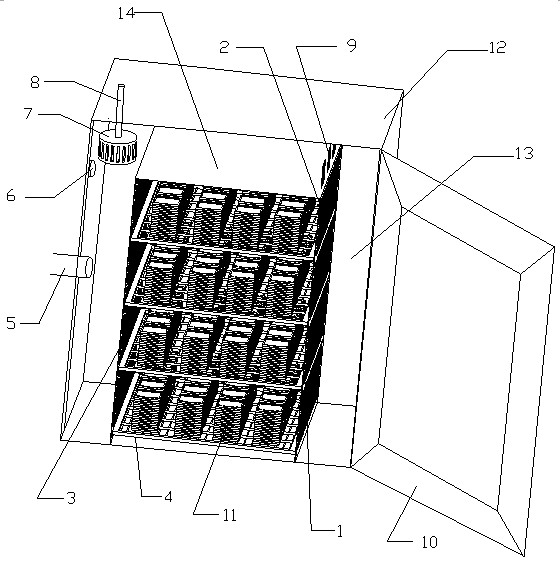
[0019] like figure 1 As shown, the debinding furnace of the present embodiment includes a furnace wall 12, a furnace door 10, a furnace wall 12 and a furnace door 10 to form a furnace 13, a blower 7 and a heater 9, and the furnace 13 is used to place electronic components to be deglued. The left furnace wall 12 is provided with an air inlet 6 and an air outlet 5, wherein the air inlet 6 is arranged on the top of the left furnace wall 12 and is close to the top of the furnace wall for introducing fresh air into the furnace under the action of the blower 7, The air outlet 5 is set in the middle part of the furnace wall 12 on the left side, and its external exhaust device is used to suck away the flue gas produced by debinding. The blower 7 is set on the top left side of the furnace 13 near the air inlet 6. The motor output shaf...


PUM


Abstract

The invention discloses a glue discharging furnace which comprises a furnace wall, a furnace door, a heart surrounded by the furnace wall and the furnace door, an air inlet, an air outlet, an air blower, a heater, an air inlet plate, an air outlet plate, a plurality of baffle plates and a plurality of air regulating plates, wherein the air inlet and the air outlet are arranged on the furnace wall; the air blower and the heater are positioned in the hearth; the air inlet plate and the air outlet plate are arranged in the hearth; the plurality of baffle plates are positioned between the air inlet plate and the air outlet plate and are used for placing to-be-discharged glue elements; the air inlet plate is provided with a plurality of air inlet holes; the air regulating plates are provided with a plurality of air regulating holes; the air regulating plates are installed on the air inlet plate and are fit with the air inlet plate so as to enable the air regulating holes and the air inlet holes to be staggered and overlapped; and the installation position of the air regulating plates on the air inlet plate can be regulated, thus the overlapped degree of staggered overlapping can be regulated. Compared with the prior art, the air speed of each layer of the glue discharging furnace provided by the invention can be regulated consistently, and the glue discharging effect is good.

Description

technical field [0001] The invention relates to a glue-removing technology for chip electronic components, in particular to a glue-removing furnace. Background technique [0002] Glue removal is an important process in the production of chip components, and the effect of glue removal directly affects the quality of chip components. Debinding furnaces in the industry often have shortcomings such as uneven air intake for each layer in the furnace and uneven temperature in the furnace. Due to these shortcomings, due to the different positions of the chip components in the debinding furnace, the extreme difference in the amount of debinding between them is often large, resulting in different final process performances of the products. Contents of the invention [0003] The technical problem to be solved by the present invention is to provide a debinding furnace to reduce the difference in air intake and temperature of each layer in the hearth of the debinding furnace. [000...

Claims


Application Information

Patent Timeline
Patent Type & Authority Applications(China)
IPC IPC(8): F27B17/00
Inventor 蒋家军曾艳军田志飞
Owner SHENZHEN SUNLORD ELECTRONICS
Why Eureka
Try Eureka