Finite element modeling method of special-shaped honeycomb skin structure
What is AI technical title?
AI technical title is built by Patsnap AI team. It summarizes the technical point description of the patent document.
A honeycomb structure and modeling method technology, applied in the field of aviation propulsion, can solve problems such as difficult to establish finite element model, difficult to analyze, difficult to establish design standards for honeycomb skin structure, etc.
Inactive Publication Date: 2014-04-30
BEIHANG UNIV
View PDF3 Cites 0 Cited by
Summary
Abstract
Description
Claims
Application Information
AI Technical Summary
This helps you quickly interpret patents by identifying the three key elements:
Problems solved by technology
Method used
Benefits of technology
Problems solved by technology
The equivalent method uses the structural homogenization theory to derive the equivalent elastic parameters of the honeycomb skin structure. Its disadvantage is that it is difficult to analyze the influence of complex stress and strain caused by stress concentration.
The experimental method can only obtain the empirical value of the material properties of the honeycomb skin structure, and it is difficult to establish the design standard of the honeycomb skin structure
[0004] Obviously, the traditional equivalent method and experimental method are difficult to meet the analysis needs of the mechanical properties of the honeycomb skin structure, so the analysis of the mechanical properties of the honeycomb skin structure should tend to use the finite element method
However, the difficulty of using the finite element method to analyze the mechanical properties of the honeycomb skin structure is that the honeycomb skin structure, especially the special-shaped honeycomb skin structure with complex cutting boundaries, is difficult to establish a finite element model. Finite element modeling of honeycomb skin structures can only be done manually, which consumes a lot of time and resources, and for some large structures, manual modeling is not even possible
Method used
Image
Click on the blue label to locate the original text in one second.
Reading with bidirectional positioning of images and text.
Examples
Embodiment Construction
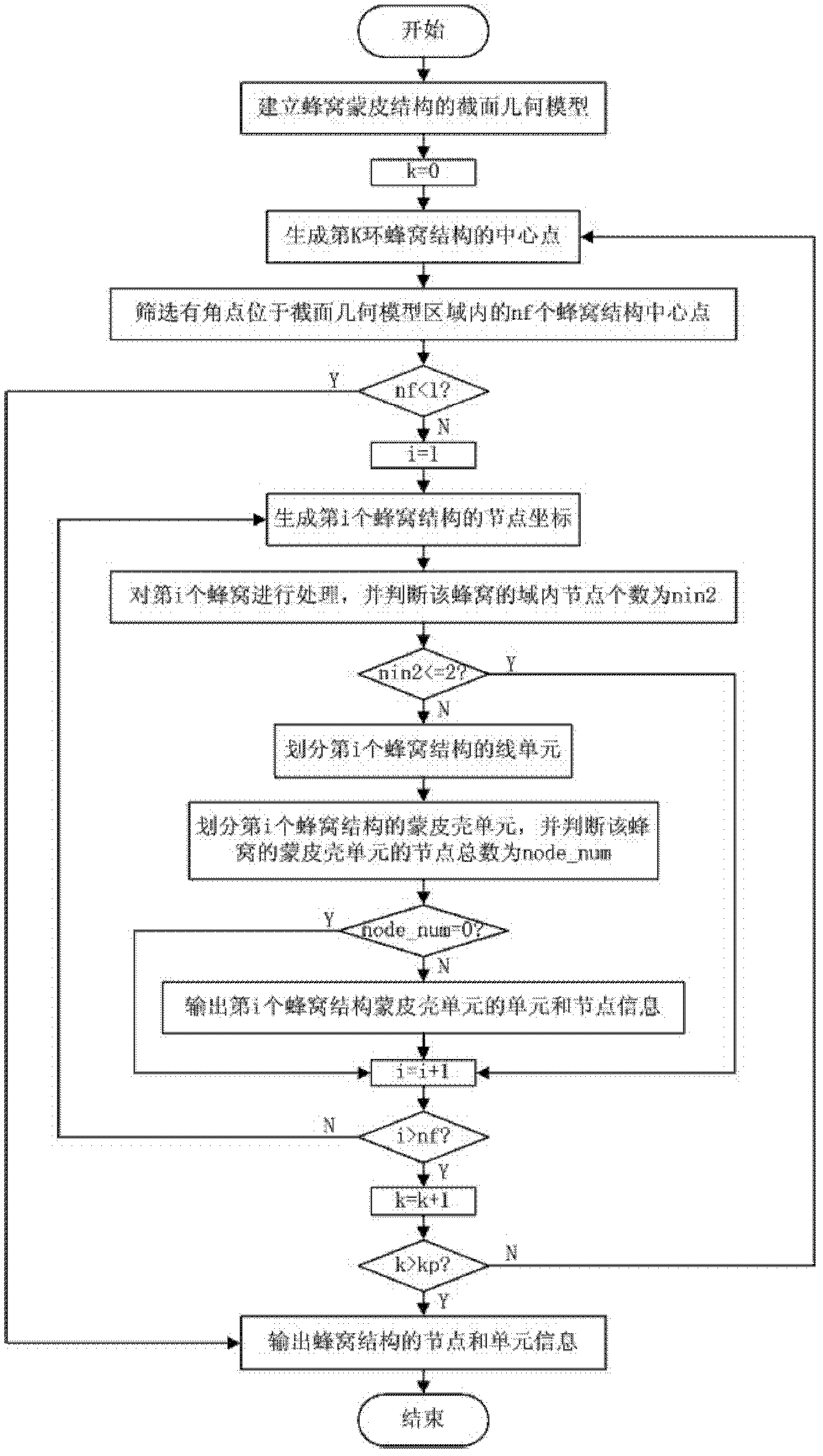
[0125] The present invention will be further described in detail below in conjunction with the accompanying drawings and examples. The present invention is a finite element modeling method of a special-shaped honeycomb skin structure, the flow chart of the method is as follows figure 1 shown.
[0126] The purpose of the present invention is to provide a finite element modeling method of a special-shaped honeycomb skin structure, which solves the deficiencies of the prior art.
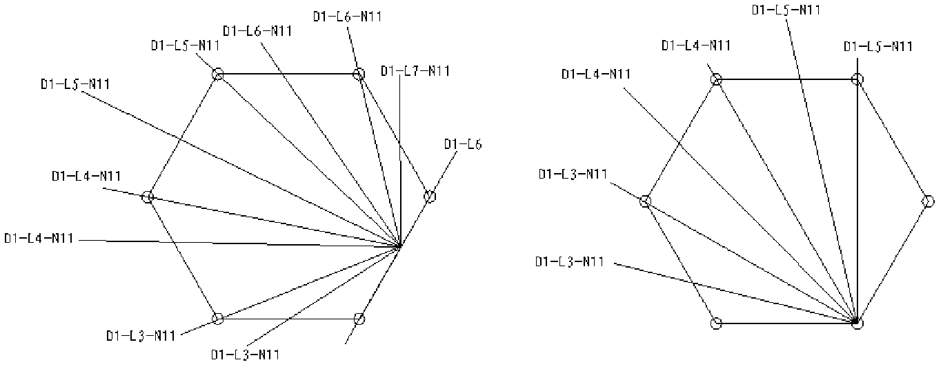
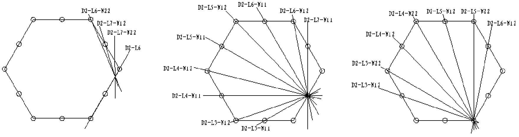
[0127] The present invention aims to generate a finite element grid of a special-shaped honeycomb skin structure. The sandwich honeycomb of this structure adopts the form of a hexagonal honeycomb, and the boundary is cut and formed. The honeycombs are connected by bonding, and there is a bonding Direction, and there is a bonding thickness between honeycombs in the bonding direction; in order to obtain different structural mechanical properties, the honeycomb structure can be arranged in any direction. ...
PUM
Abstract
The invention discloses a finite element modeling method of a special-shaped honeycomb skin structure, comprising the following steps of: step1, building a section geometric model of the special-shaped honeycomb skin structure; step2, generating a honeycomb central point of a certain ring; step3, screening intra-domain honeycombs; step4, executing step15 if no intra-domain honeycomb exists in the current ring, otherwise, executing step5; step5, generating a node for the intra-domain honeycomb in the current ring; step6, processing the honeycomb node; step7, executing step8 if the number of the intra-domain nodes is more than 2, otherwise, executing step13; step8, dividing linear units of the honeycomb; step9, dividing the corresponding skin units; step10, executing step11 if the number of skin unit nodes is 0, otherwise, executing step13; step11, outputting information of the skin units; step12, outputting information of skin nodes; step13, executing step5 if honeycombs of the current ring are not completely processed, otherwise, executing step14; step14, executing step2 if honeycombs of all rings are not completely processed, otherwise, executing step15; step15, outputting information of the honeycomb units; step16, outputting information of the honeycomb nodes; step17, outputting information of a unit collection in bounding parts of the honeycomb.
Description
(1) Technical field [0001] The invention relates to a finite element modeling method of a special-shaped honeycomb skin structure, belonging to the technical field of aviation propulsion. (2) Background technology [0002] The honeycomb skin structure is composed of two thin and strong panel materials sandwiched by a thick and light honeycomb core. The biggest feature of this type of material is light weight, high specific strength and high specific stiffness. In the 1900s, high-performance honeycomb manufacturing technology has matured, and honeycomb structures are widely used in aircraft, aviation and aerospace industries. Compared with traditional materials, honeycomb skin materials have the advantages of low density, low thermal conductivity, high specific stiffness, high specific strength, large compressive strain, good energy absorption characteristics, high designability, etc., and are suitable for the aerospace field. An important composite material. [0003] At pr...
Claims
Application Information
Patent Timeline
Application Date:The date an application was filed.
Publication Date:The date a patent or application was officially published.
First Publication Date:The earliest publication date of a patent with the same application number.
Issue Date:Publication date of the patent grant document.
PCT Entry Date:The Entry date of PCT National Phase.
Estimated Expiry Date:The statutory expiry date of a patent right according to the Patent Law, and it is the longest term of protection that the patent right can achieve without the termination of the patent right due to other reasons(Term extension factor has been taken into account ).
Invalid Date:Actual expiry date is based on effective date or publication date of legal transaction data of invalid patent.

