
Framework structure of amorphous alloy transformer

A skeleton structure, amorphous alloy technology, applied in transformer/inductor components, transformer/inductor cores, electrical components, etc., can solve problems such as skeleton compression of iron core columns, increase in coil circumference, and increase in load loss , to achieve the effect of reducing assembly time, reducing no-load loss, and avoiding increasing

Inactive Publication Date: 2012-09-12
SHANGHAI ZHIXIN ELECTRIC AMORPHOUS +2
View PDF5 Cites 8 Cited by
  • Summary
  • Abstract
  • Description
  • Claims
  • Application Information

AI Technical Summary

Problems solved by technology

But a single frame may be slightly deformed and pressed to the core column
In this regard, if the method of increasing the wall thickness of the skeleton is adopted, the circumference of the coil will increase, thereby increasing the load loss and increasing the cost due to the increase in the weight of the coil.

Method used


Image

  • Framework structure of amorphous alloy transformer
  • Framework structure of amorphous alloy transformer
  • Framework structure of amorphous alloy transformer

Examples


Embodiment Construction

[0010] In order to enable those skilled in the art to better understand the technical solution of the present invention, its specific implementation will be described in detail below in conjunction with the accompanying drawings:

[0011] Usually, the iron core columns of each phase coil in the amorphous alloy transformer are assembled by an even number of individual iron core columns with the same shape and size, and the assembled iron core columns are rectangular in shape.

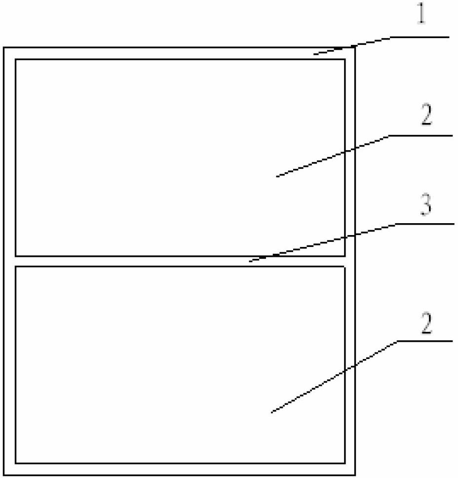
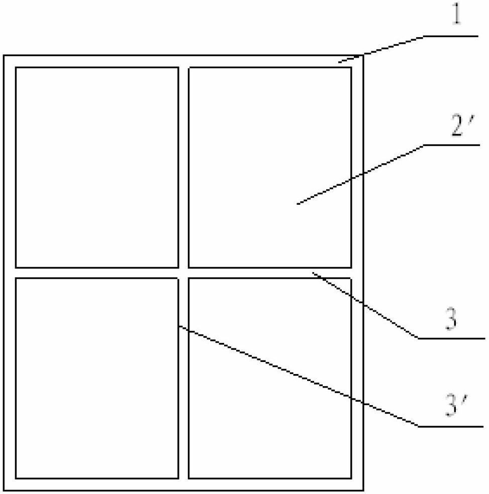
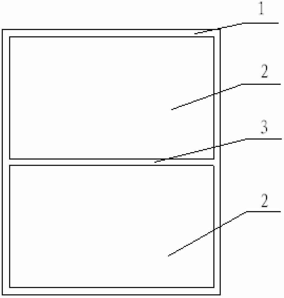
[0012] see figure 1 , the skeleton structure of the amorphous alloy transformer of the present invention is a hollow cylinder, the cross-sectional shape of the skeleton inner chamber is rectangular, and the inner chamber of the skeleton 1 is separated into several unit spaces 2 of the same shape by a partition plate 3, if a single There are two body core columns, and there are also two unit spaces 2, so that the two single core columns can be inserted into the unit space 2 one by one accordingly.

[001...


PUM


Abstract

The invention discloses a framework structure of an amorphous alloy transformer. The framework structure of the amorphous alloy transformer is a hollow barrel, the section shape of an inner cavity of a framework matches with the section shapes of iron core columns used for sleeving each phase of coils, each iron core column is formed by splicing of a plurality of iron core column units which have the same shape and the same dimensions, and the inner cavity of the framework is partitioned into a plurality of space units through partitions according to the number and the shape of the iron core column units, so that each of the iron core column units can be inserted in one of the space units of the framework correspondingly. Each iron core column cannot be subjected to mutual friction and extrusion to produce stress, so that no-load loss is reduced. Additionally, rigid strength of the framework is enhanced, so that resistance to electromotive force produced by the coils can be strengthened when the transformer is short-circuited unexpectedly, increasing of the no-load loss caused by extra-stress of iron cores is prevented, and time for assembling a transformer body is greatly shortened by the preprocessed framework.

Description

technical field [0001] The invention belongs to the field of transformers and relates to a skeleton structure of an amorphous alloy transformer. Background technique [0002] Generally, the coil of amorphous alloy transformer is set on the iron core column of amorphous alloy. On the skeleton, the skeleton is a rectangular cylinder matching the cross-sectional shape of the iron core column of the transformer. The low-voltage coil is not easily deformed, the short circuit is avoided, and the deformation of the amorphous alloy iron core can be prevented. When a sudden short circuit occurs in the transformer, the low-voltage coil will generate strong electromotive force and shrink inwardly to press the iron core column, which will increase the no-load loss and generate iron core fragments. At this time, the skeleton in the low-voltage coil will share the Part of the electric power plays a protective role. But the single skeleton may thus be slightly deformed and compressed to...

Claims


Application Information

Patent Timeline
IPC IPC(8): H01F27/26H01F27/00
Inventor 林雪军蔡煜杜吉红
Owner SHANGHAI ZHIXIN ELECTRIC AMORPHOUS
Learn More