
Method for manufacturing resonant cavity light emitting diode

A technology for light-emitting diodes and manufacturing methods, which is applied in the direction of electric solid-state devices, semiconductor devices, electrical components, etc., and can solve problems such as alignment errors, increased series resistance, and poor light-emitting efficiency of resonant cavity light-emitting diodes.

Inactive Publication Date: 2014-12-31
CHUNGHWA TELECOM CO LTD
View PDF5 Cites 0 Cited by
  • Summary
  • Abstract
  • Description
  • Claims
  • Application Information

AI Technical Summary

Problems solved by technology

In the manufacturing process of the above-mentioned components, the upper Bragg reflector layer is to be plated in the light-exiting area to form an effective resonant cavity with the lower Bragg reflector layer. At the same time, it is necessary to ensure that the current can be injected into the metal contact electrode on the component by an external circuit, but due After ion etching, a significant height difference has been caused between the light-emitting area of ​​the component and the contact area of ​​the N-type electrode. This height difference will increase the difficulty of precisely defining the Bragg reflector layer on the light-emitting area with lithography technology. The bit error makes part of the insulating material plated on the metal electrode and increases the series resistance. In addition, the light-emitting efficiency of the resonant cavity light-emitting diode will also deteriorate because the light-emitting area is not plated on the upper Bragg reflector layer.

Method used


Image

  • Method for manufacturing resonant cavity light emitting diode
  • Method for manufacturing resonant cavity light emitting diode
  • Method for manufacturing resonant cavity light emitting diode

Examples


Embodiment Construction

[0066] The foregoing and other technical contents, features and effects of the present invention will be clearly understood in the following detailed description of preferred embodiments with reference to the drawings.

[0067] The first preferred embodiment of the method for manufacturing a resonant cavity light-emitting diode of the present invention can simplify the manufacturing process of the upper Bragg reflector layer, and the upper Bragg reflector layer can be formed on the light-emitting diode without an alignment step The light-extracting area of ​​the body, and a resonant cavity light-emitting diode with high light-extracting efficiency is manufactured.

[0068] refer to figure 2 Step 211 is performed to sequentially epitaxially grow the lower Bragg reflector layer 31, the N-type cladding layer 32, the light-emitting layer 33 and the P-type cladding layer 34 on the epitaxial substrate 30, so as to jointly form the active region 3, as image 3 shown. The epitaxial...


PUM


Abstract

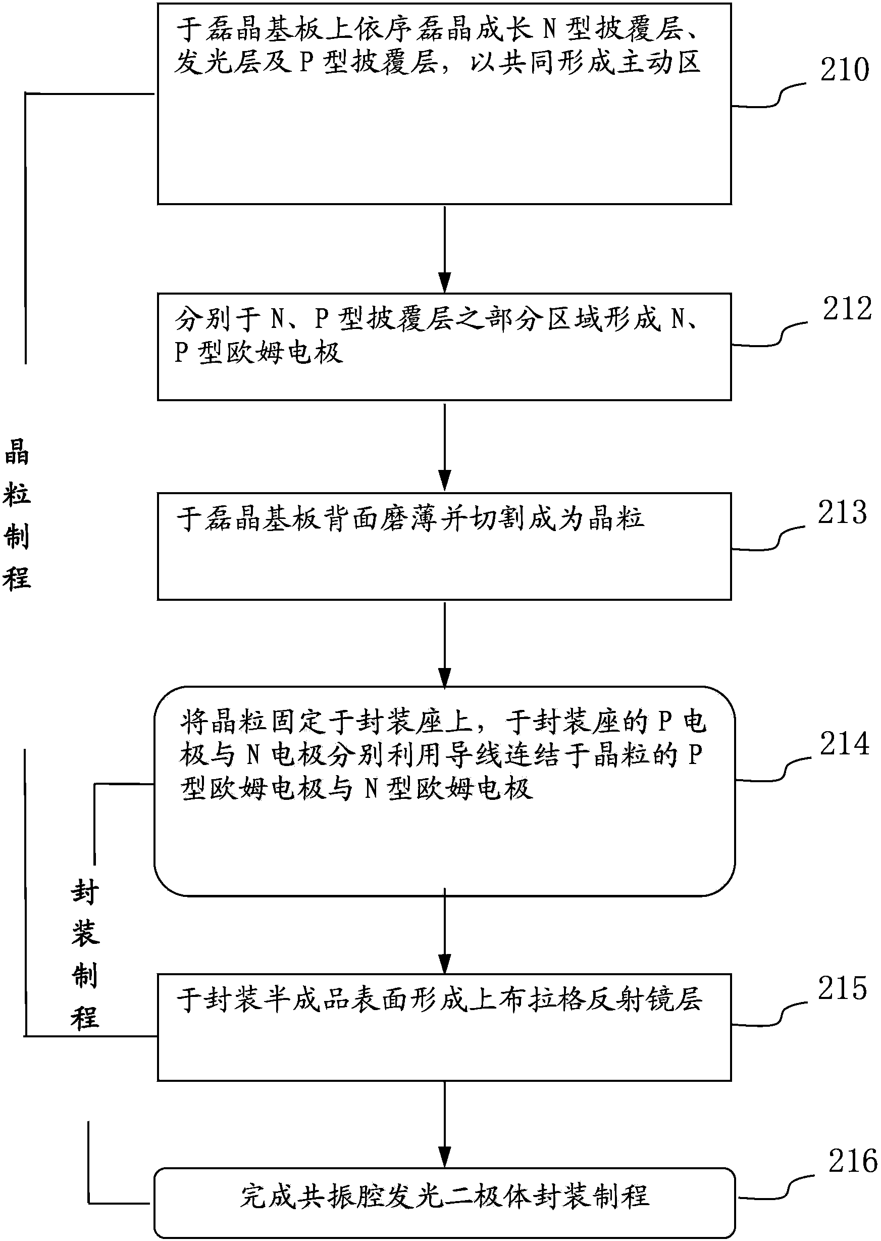
The present invention relates to a method for manufacturing a resonant cavity light emitting diode, which changes the manufacturing steps of the resonant cavity light emitting diode, wherein in the process of manufacturing crystalline grains, an upper Bragg reflector layer is manufactured after finishing package manufacturing process steps, such as crystalline grain solid phase crystallization, routing and bonding, etc., thereby resolving the problem that when an upper reflector is defined in a light outgoing area with lithography, in the prior art, aligning errors are easily generated, and improving the operation characteristics of the resonant cavity light emitting diode.

Description

technical field [0001] The invention belongs to the field of optoelectronics, in particular to a method for manufacturing a resonant cavity light-emitting diode. Background technique [0002] Light-emitting diodes are spontaneous emission light sources, and the light emitted by them has isotropic properties. Due to the limited total reflection effect, the light emitted inside can only leave the semiconductor surface within the "escape cone" formed by the critical angle, and the light that cannot escape will eventually be absorbed by the material. In order to increase the light extraction efficiency, an effective and practical method is to add reflectors above and below the traditional light-emitting diode light-emitting layer to form a light-emitting diode structure with a resonant cavity, and use the interference effect of light in the resonant cavity to change The light-emitting angle distribution of the light field enables most of the light to be confined in the escape c...

Claims


Application Information

Patent Timeline
Patent Type & Authority Patents(China)
IPC IPC(8): H01L33/00H01L33/10
CPCH01L2924/181H01L2224/0603H01L2224/48091H01L2224/48463H01L2224/49107H01L2224/73265H01L2924/00012H01L2924/00014
Inventor 蔡家龙柯孙坚徐仲凡
Owner CHUNGHWA TELECOM CO LTD
Learn More