
OLED display panel and preparation method thereof

A technology for display panels and array substrates, used in semiconductor/solid-state device manufacturing, electrical components, electrical solid-state devices, etc. Effect

Pending Publication Date: 2021-02-26
WUHAN CHINA STAR OPTOELECTRONICS SEMICON DISPLAY TECH CO LTD
View PDF19 Cites 0 Cited by
  • Summary
  • Abstract
  • Description
  • Claims
  • Application Information

AI Technical Summary

Problems solved by technology

[0003] The application of OLED display panels in small sizes is mainly achieved through vacuum evaporation technology. After more than ten years of development, this technology has become relatively mature, and mobile phone screens, vehicle displays, and VR have basically achieved industrialization; in the field of large sizes, it is mainly achieved through inkjet It is prepared by printing, dissolving the organic light-emitting material in the solution, and then dripping the solution into the corresponding pixel area. Compared with vacuum evaporation, this technology has many advantages: higher material utilization rate, no need to use high-precision metal mask plate , film forming process is simple, etc. At present, inkjet printing technology also has many problems. When preparing OLED light-emitting device layers, it is necessary to accurately drop the solution of the corresponding color into the pixel limited area. It will form "climbing" and cause uneven film thickness, which greatly affects product performance
[0004] To sum up, it is necessary to design a new OLED display panel structure to solve the problem that in the preparation process of large-size OLED display panels in the prior art, the preparation method of the light-emitting device layer generally adopts inkjet printing technology. The solution containing the luminescent material is dropped into the pixel area to form the corresponding luminescent layer, but due to the surface tension of the luminescent material solution, the droplet dripped into the pixel area will form a "climbing slope" after drying, resulting in uneven thickness, which greatly affects product performance

Method used


Image

  • OLED display panel and preparation method thereof
  • OLED display panel and preparation method thereof
  • OLED display panel and preparation method thereof

Examples


Embodiment Construction

[0026] The following will clearly and completely describe the technical solutions in the embodiments of the present invention with reference to the drawings in the embodiments of the present invention. Apparently, the described embodiments are only some of the embodiments of the present invention, but not all of them. Based on the embodiments of the present invention, all other embodiments obtained by those skilled in the art without creative efforts fall within the protection scope of the present invention.

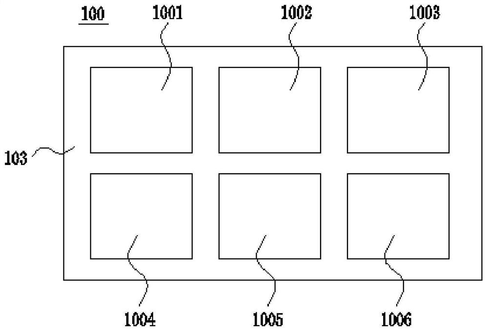
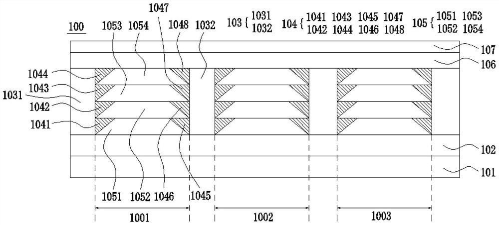
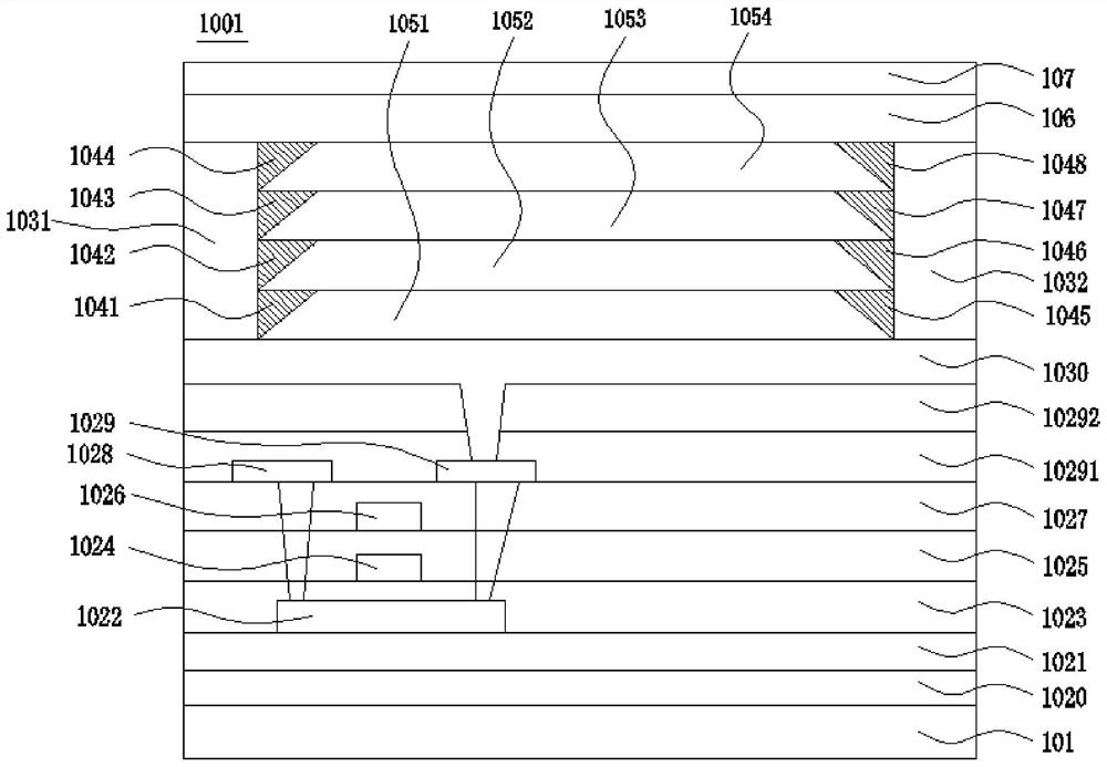
[0027] The present invention is aimed at the preparation process of the large-size OLED display panel in the prior art. The preparation method of the light-emitting layer generally adopts the inkjet printing technology. In this technology, a solution containing a light-emitting material is dropped into the pixel area to form a corresponding light-emitting device layer. However, due to the surface tension of the luminescent material solution, the droplets dripped into the...


PUM


Abstract

The invention provides an OLED display panel and a preparation method thereof, a light emitting function layer in the OLED display panel comprises a pixel definition layer formed on an array substrate, an array-shaped pixel region is formed on the pixel definition layer, a light emitting device is formed in the pixel region, a barb structure is formed on the inner side of the pixel region, and thebarb structure is connected with the edge of the light emitting device. One side, facing the pixel region, of the barb structure is arc-shaped or slope, after an organic solution of the light-emitting layer and an electro-function layers positioned on two sides of the light-emitting layer is dripped into the pixel region, the organic solution is arranged along the arc-shaped surface or the slopesurface, and the distribution form effectively avoids the phenomenon of 'climbing' caused by surface tension, so that the film thickness uniformity of the light-emitting function layers of the OLED panel is improved; and in addition, the barb structure is prepared from a transparent material, and the light emitting efficiency of the light emitting device is not influenced.

Description

technical field [0001] The invention relates to the field of display technology, in particular to an OLED display panel and a preparation method thereof. Background technique [0002] Organic Light Emitting Display (OLED) display panel has many advantages such as self-illumination, low driving voltage, high luminous efficiency, short response time, high definition and contrast, nearly 180° viewing angle, and wide operating temperature range. The device adopts the structure of anode, organic light-emitting layer and cathode. When the current is applied to both ends, electrons and holes are injected into the organic light-emitting layer. Different organic light-emitting materials emit light of different colors under the excitation of excitons, thus being applied to Various display products. [0003] The application of OLED display panels in small sizes is mainly achieved through vacuum evaporation technology. After more than ten years of development, this technology has becom...

Claims


Application Information

Patent Timeline
Patent Type & Authority Applications(China)
IPC IPC(8): H01L27/32H01L51/52H01L51/56
CPCH10K59/122H10K59/12H10K50/84H10K71/00
Inventor 王德祺
Owner WUHAN CHINA STAR OPTOELECTRONICS SEMICON DISPLAY TECH CO LTD
Learn More