Reduced-pressure drying unit and coating film forming method

Inactive Publication Date: 2005-04-28
TOKYO ELECTRON LTD
View PDF7 Cites 17 Cited by
  • Summary
  • Abstract
  • Description
  • Claims
  • Application Information

AI Technical Summary

Benefits of technology

[0017] According to the present invention, an exhaust current flowing outward from the center is formed between the current member and the substrate during the reduced-pressure drying processing, but the liquid flow of the coating solution on the substrate is controlled by changing the height position of the current member in the reduced-pressure drying processing, thereby controlling the film thickness of the coating film on the front face of the substrate. This prevents a rounded shape or an accumulated portion of the coating solution at a peripheral region of the substrate, so that the film thicknesses of the coating solution are made uniform between the center region and the peripheral region, resulting in improved uniformity of film thickness.
[0018] Further, according to the present invention, the substrate is heated by the heater provided in the mount, but the peripheral region of the substrate is in contact with the annular member which has a heat conductivity different from that of the mount, thereby causing different temperatures and accordingly different vaporization rates of the solvent co

Problems solved by technology

Hence, there is a request that the circuit formation region occupies an area as large as possible to improve the yield of chips per wafer, and thus a signif

Method used


Image

  • Reduced-pressure drying unit and coating film forming method
  • Reduced-pressure drying unit and coating film forming method
  • Reduced-pressure drying unit and coating film forming method

Examples


Embodiment Construction

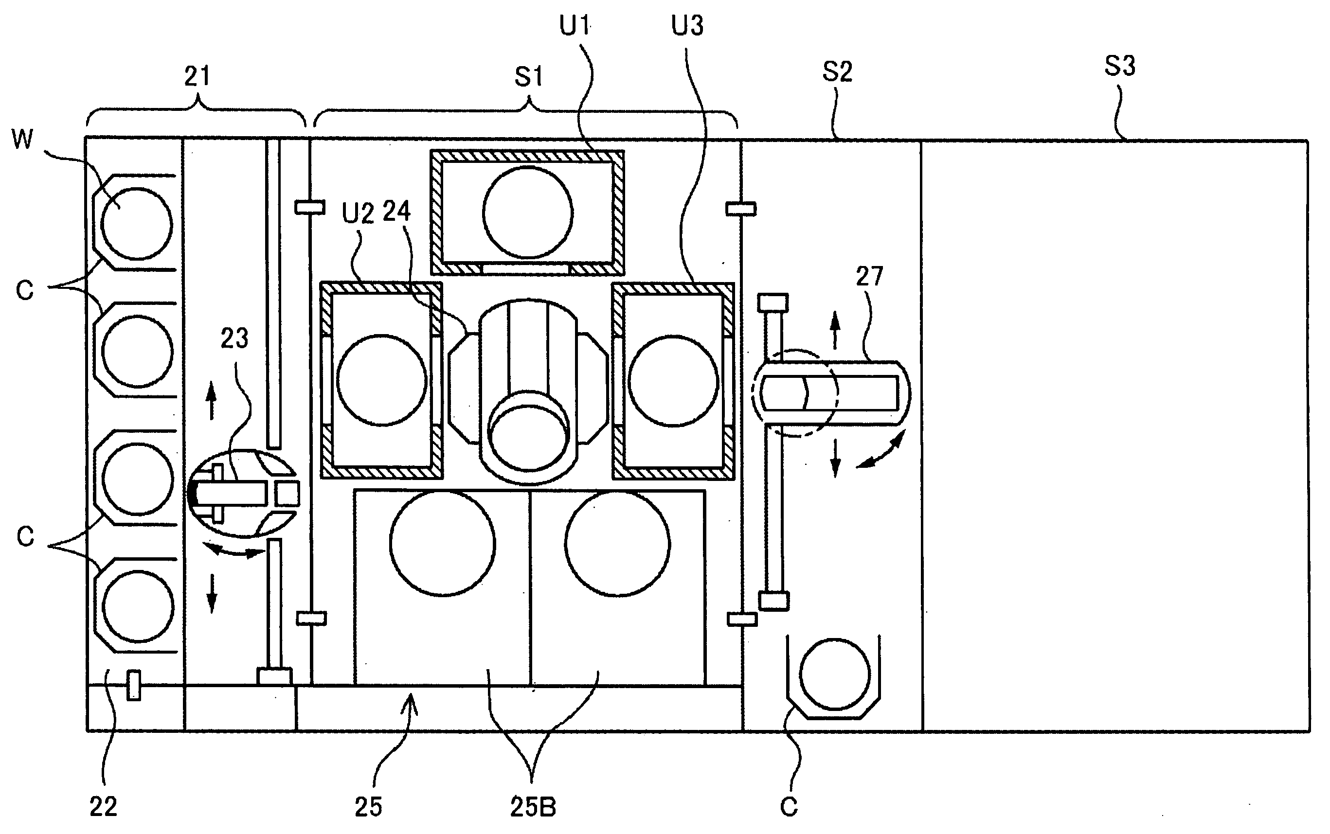
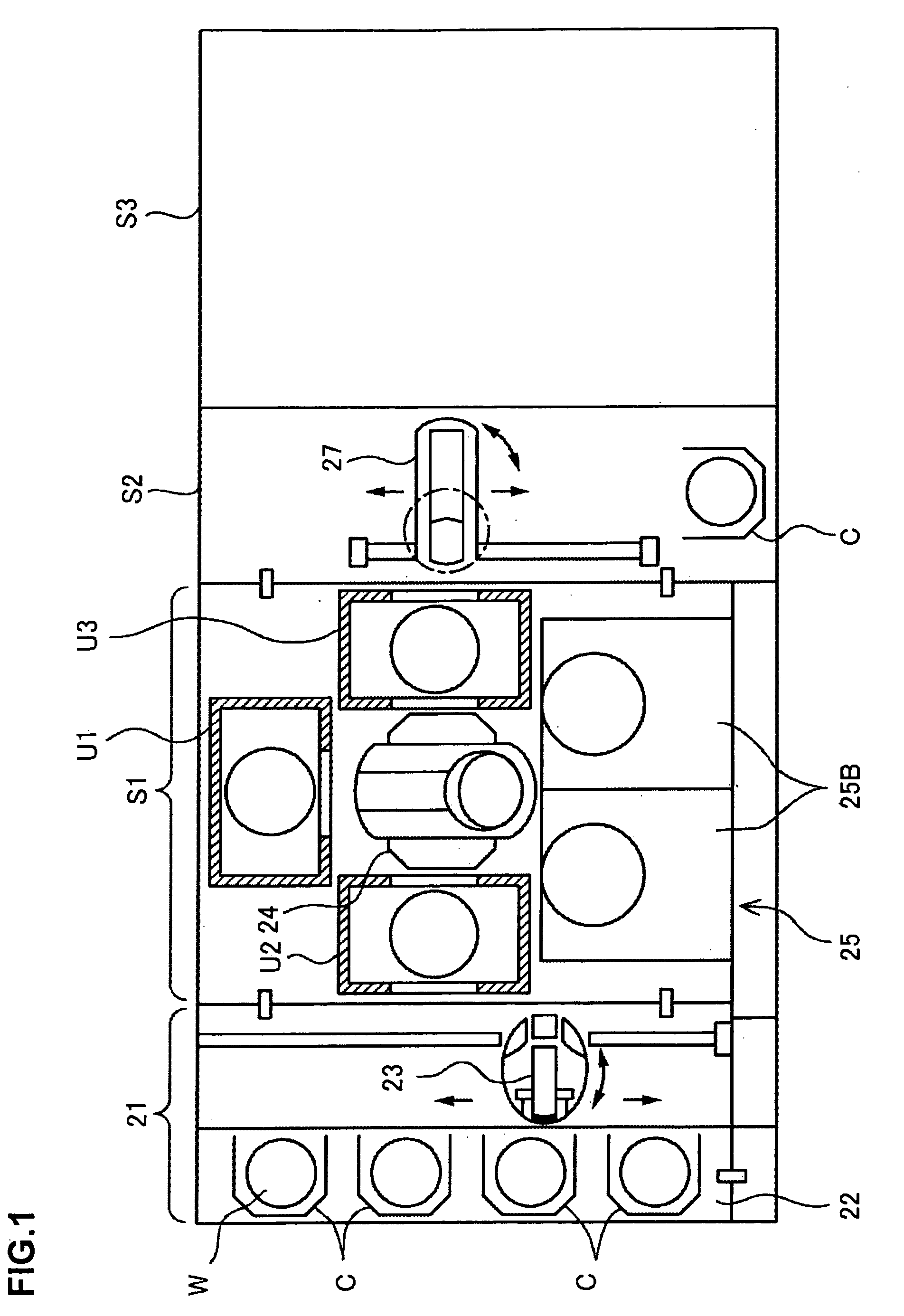
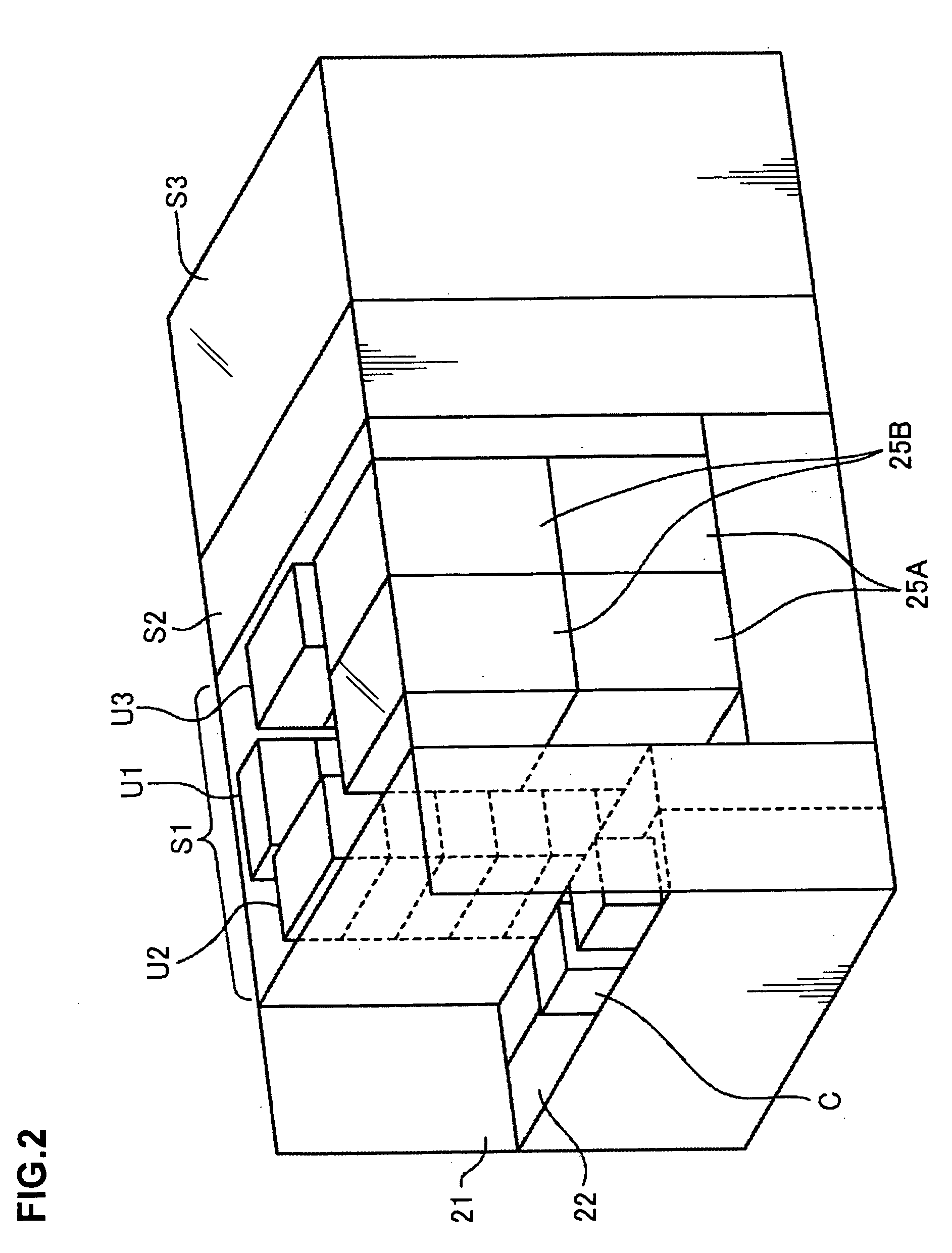
[0054] First of all, an entire configuration of a coating film forming apparatus in which a reduced-pressure drying unit according to the present invention is installed will be briefly explained below with reference to FIG. 1 to FIG. 3. In the drawings, numeral 21 denotes a cassette station, in which a cassette mounting section 22 for mounting thereon cassettes C in which, for example, 25 wafers W are housed and a delivery arm 23 for delivering and receiving the wafers W to / from the mounted cassette C are provided. A processing section S1 is connected to the back side of the delivery arm 23. A main carrier 24 is provided in the center part of the processing section S1 and, in such a manner to surround the main carrier 24, a coating and developing system unit 25 including a plurality of coating units 25A and developing units 25B is disposed, for example, on the right-hand side as seen to the back side and shelf units U1, U2, and U3 including heating and cooling system units and the l...


PUM

PropertyMeasurementUnit
Thicknessaaaaaaaaaa
Pressureaaaaaaaaaa

Abstract

The invention includes a hermetic container provided with a substrate mount; a vacuum exhauster connected to the hermetic container; a current member; and a current member raising and lowering mechanism. When the current member is raised and lowered as a function of the pressure inside the hermetic container, a liquid flow of the coating solution on the substrate is controlled, thereby controlling the uniformity of the film thickness of the coating solution.

Description

BACKGROUND OF THE INVENTION [0001] 1. Field of the Invention [0002] The present invention relates to a reduced-pressure drying unit and a coating film forming method for vaporizing a solvent from a coating solution when the coating solution made by, for example, mixing a component of a coating film in the solvent, for example, a resist solution is applied to a substrate such as a semiconductor wafer or an LCD substrate (a glass substrate for a liquid crystal display) to form the coating film. [0003] 2. Description of the Related Art [0004] In fabrication processes of semiconductor devices and LCDs, resist processing is performed for a substrate to be processed by a technique called photolithography. This technique includes a series of steps of applying a resist solution to, for example, a semiconductor wafer (hereinafter, referred to as a wafer) to form a solution film on its front face, exposing the resist film to light using a photomask, and thereafter performing a developing trea...

Claims


Application Information

Patent Timeline
IPC IPC(8): B05D3/04H01L21/027H01L21/00
CPCH01L21/67034B05D3/0493H01L21/027
Inventor KITANO, TAKAHIROHAMA, MANABUSUGIMOTO, SHINICHIHIRAKAWA, NAOYA
Owner TOKYO ELECTRON LTD
Why Eureka
Try Eureka