Multi-frequency-band piezoelectric vibration energy collector

An energy harvester, piezoelectric vibration technology, applied in the direction of generators/motors, piezoelectric effect/electrostrictive or magnetostrictive motors, electrical components, etc., can solve problems such as limited applications, and achieve easy application and high efficiency collection of effects

Inactive Publication Date: 2012-09-12
SHANGHAI JIAO TONG UNIV
View PDF4 Cites 21 Cited by
  • Summary
  • Abstract
  • Description
  • Claims
  • Application Information

AI Technical Summary

Problems solved by technology

Because the time for a flapper to generate electricity is short, it needs continuous flapping to generate stable electric energy, but it is generally only suitable for low-frequency vibrations, especially the flapper needs to have a larger amplitude to vibrate. have limited its application

Method used


Image

  • Multi-frequency-band piezoelectric vibration energy collector
  • Multi-frequency-band piezoelectric vibration energy collector
  • Multi-frequency-band piezoelectric vibration energy collector

Examples


Embodiment 1

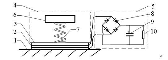
[0022] like figure 1 As shown, this embodiment includes: a vibrating element 1, a piezoelectric element 2, a cover plate 3, a dynamic vibration absorber 4 and an energy harvesting circuit 5, wherein: the vibrating element 1 is connected to the piezoelectric element 2, and the piezoelectric element 2 is fixed with a cover The plate 3 and the cover plate 3 are connected with the dynamic vibration absorber 4 , and the energy harvesting circuit 5 is connected with the piezoelectric element 2 .

[0023] The dynamic vibration absorber 4 includes: a mass block 6 and an elastic element 7 , wherein: the elastic element 7 is connected to the cover plate 3 , and the mass block 6 is connected to the elastic element 7 .

[0024] The damping ratio of the elastic element 7 is less than 0.3.

[0025] Piezoelectric element 2 of the present embodiment adopts thickness stretching mold, and its piezoelectric constant is d 33 。

[0026] The energy harvesting circuit 5 is a full-br...

Embodiment 2

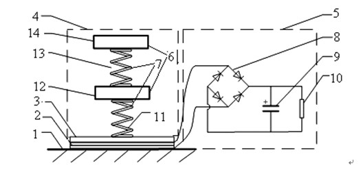
[0031] like figure 2 As shown, the dynamic vibration absorber 4 of this embodiment is a superposition of two elastic elements 7 and a mass block 6, forming a double-layer dynamic vibration absorbing structure. The dynamic shock absorber 4 includes a first spring 11, a first mass block 12, a second spring 13 and a second mass block 14, wherein: the first spring 11 is connected to the cover plate 3, the first spring 11, the first mass block 12, The second spring 13 and the second mass block 14 are connected in sequence. That is, the elastic element 7 includes: a first spring 11 and a second spring 13 , and the mass block 6 includes: a first mass block 12 and a second mass block 14 .

[0032] Other implementation modes of this embodiment are the same as Embodiment 1.

[0033] In this embodiment, two springs, a mass block 6 and a vibrating element 1 are used to form a three-degree-of-freedom vibration system, which increases the number of formants and the width of the res...

Embodiment 3

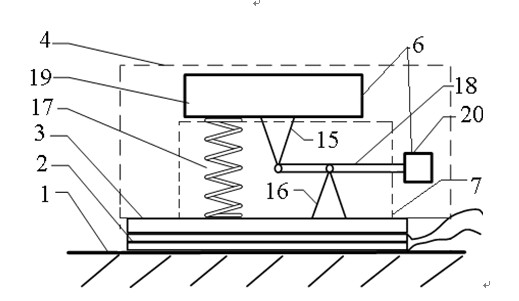
[0035] like image 3 As shown, the elastic element 7 of this embodiment includes: a first bracket 15, a second bracket 16, a third spring 17 and a first lever 18, and the mass block 6 includes: a third mass block 19 and a fourth mass block 20, wherein : the first support 15 and the fourth mass block 20 are respectively located at the two ends of the first lever 18, the second support 16 is connected with the first lever 18 and the cover plate 3 respectively, the first support 15 is connected with the third mass block 19, the second The three masses 19 are connected to the third spring 17 , and the third spring 17 is connected to the cover plate 3 .

[0036] Other implementation modes of this embodiment are the same as Embodiment 1.

[0037] This structure is suitable for applications where weight is limited.


PUM


Abstract

The invention discloses a multi-frequency-band piezoelectric vibration energy collector which comprises a piezoelectric element, a cover plate, a dynamic absorber, an energy collecting circuit and a lateral wall, wherein the piezoelectric element is composed of a piezoelectric cantilever beam structure and a second piezoelectric stack; the piezoelectric cantilever beam structure consists of a piezoelectric sheet and a cantilever beam; the second piezoelectric stack is adhered to the lateral wall; the second piezoelectric stack is provided with the cover plate; the dynamic absorber comprises a mass block and an elastic element with the damping ratio less than 0.3, wherein the mass block and the elastic element are connected; and the elastic element comprises a fifth support, a sixth support and the cantilever beam. According to the invention, the working frequency can be designed in multiple frequency bands, and the collection of easily applied and efficient vibration energy can be realized.

Description

[0001] This application is a divisional application of the invention patent application with the application number 201010130519.3, the application date is March 24, 2010, and the invention title is "Piezoelectric Vibration Energy Harvesting Device Based on Dynamic Vibration Absorber". technical field [0002] The invention relates to a device in the technical field of energy utilization, in particular to a multi-band piezoelectric vibration energy harvester. Background technique [0003] The common characteristics of micro-electromechanical systems such as wireless sensor networks, micro-electro-mechanical systems, and personal mobile devices are: the energy consumption is very low, from a few μW to hundreds of mW, but the use time is required to be very long, and the key is due to the limitation of the use conditions They generally cannot be powered by power lines. The current battery power supply method has the disadvantages of large volume and short life, while the use o...

Claims


Application Information

Patent Timeline
Patent Type & Authority Applications(China)
IPC IPC(8): H02N2/18
Inventor 刘海利陈加浪王兆强陈大跃阳天亮徐天柱
Owner SHANGHAI JIAO TONG UNIV
Why Eureka
Try Eureka