
High-efficiency direct-fired thermoelectric semiconductor power generator

A technology of thermoelectric semiconductors and power generation devices, which is applied in the direction of generators/motors, electrical components, etc., to achieve the effects of simple structure, improved power generation efficiency, and convenient use

Inactive Publication Date: 2012-09-12
江西纳米克热电电子股份有限公司
View PDF3 Cites 5 Cited by
  • Summary
  • Abstract
  • Description
  • Claims
  • Application Information

AI Technical Summary

Problems solved by technology

[0006] The purpose of the present invention is to overcome the fact that the size of the thermoelectric module used in the semiconductor small-scale thermoelectric power generation device is small compared to the fire source, and the thermoelectric power generation device is directly placed in the Above the fire source, the scattered heat from the fire source is not easy to concentrate, which leads to unstable temperature of the hot surface of the thermoelectric module, low efficiency of heat utilization, and insufficient temperature difference between the cold and hot surfaces to affect power generation efficiency. A high-efficiency direct-fired thermoelectric power generation device is provided , can use the fire source as the heat source, use a special heat collector with a heat collecting cover and fins to provide efficient and stable heat, and use a radiator with a fan to ensure the temperature difference between the cold and hot surfaces of the device to increase output power and energy conversion efficiency

Method used


Image

  • High-efficiency direct-fired thermoelectric semiconductor power generator
  • High-efficiency direct-fired thermoelectric semiconductor power generator
  • High-efficiency direct-fired thermoelectric semiconductor power generator

Examples


Embodiment Construction

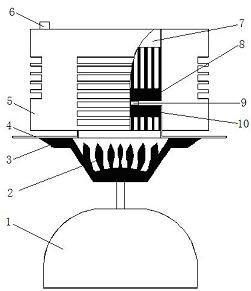
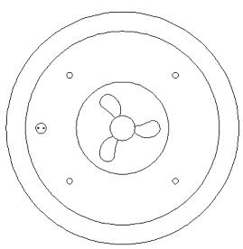
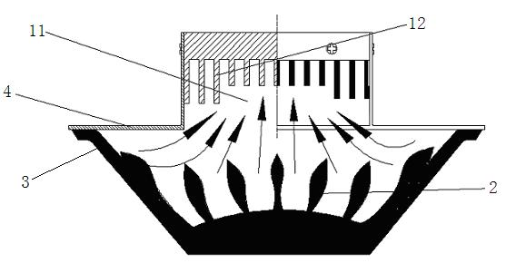
[0022] The specific embodiment of the present invention is as Figure 1~Figure 3 shown.

[0023] A high-efficiency direct-fired thermoelectric semiconductor power generation device in an embodiment of the present invention consists of a fuel tank 1, a bracket 3, a heat collecting cover 4, a casing 5, a fan 7, a heat collector 10, a radiator 8, a thermoelectric module 9, and an aviation socket Composed of 6.

[0024] The embodiment of the present invention collects heat through a heat collector 10 with a heat collecting cover 4 and fins 12. A thermoelectric module 9 is installed above the heat collector 10. Graphite paper is pasted on both the hot and cold sides of the thermoelectric module 9. The thermoelectric module 9 The hot surface of the thermoelectric module 9 is bonded to the heat collector 10 through graphite paper, and the cold surface of the thermoelectric module 9 is bonded to the radiator 8 through graphite paper. The fan 7 is installed outside the radiator 8, and...


PUM


Abstract

A high-efficiency direct-fired thermoelectric semiconductor power generator comprises a heat collector, a radiator and a thermoelectric module. The heat collector with a collector cover (4) and fins (12) is used for collecting heat, the radiator (8) with fins and a fan (7) is used for radiating heat, the thermoelectric module (9) is mounted above the heat collector (10), graphite paper is stuck on both a cold face and a hot face of the thermoelectric module (9), the hot face of the thermoelectric module (9) is attached to the heat collector (10) through the graphite paper, the cold face of the thermoelectric module (9) is attached to the radiator (8) through the graphite paper, the fan (7) is mounted outside the radiator (8), and the thermoelectric module (9) is connected with a socket (6) through a lead to deliver electric energy to the outside. The high-efficiency direct-fired thermoelectric semiconductor power generator is stable in provided voltage, simple in structure, long in service life, small in size and convenient to carry and economically affordable, and applied to places without power supply and being badly in need of electric power, such as outdoors, remote areas and emergency situations where electricity can be directly generated only by requiring fire sources for supplying heat.

Description

[0001] technical field [0002] The invention relates to the technical field of semiconductor thermoelectric power generation, in particular to a high-efficiency direct-fired thermoelectric semiconductor power generation device. Background technique [0003] Semiconductor small thermoelectric generators are widely used in outdoor, remote areas and emergency situations where there is no power supply and power is urgently needed due to its small size, easy portability, simple operation, and direct power generation with only a fire source providing heat. welcome. However, in order to save cost and be easy to carry, the thermoelectric modules used in existing semiconductor small-scale thermoelectric power generation devices are usually relatively small in size compared to the fire source. It is very difficult to collect heat, which leads to low efficiency of actual use of heat. The reduction of the actual heat of the thermoelectric module directly leads to a decrease in the...

Claims


Application Information

Patent Timeline
Patent Type & Authority Applications(China)
IPC IPC(8): H02N11/00
Inventor 郑俊辉陈俊海陈燕木颉钦冠
Owner 江西纳米克热电电子股份有限公司
Learn More