Video signal processing method and photographic equipment

A technology for video signal processing and camera equipment, applied in the field of cameras, can solve the problems of unclear images and lack of some images at the splicing place, and the scenes farther than the distance will repeat some images at the splicing place, low resolution, etc., so as to avoid Overlapping or missing seams, increasing resolution, avoiding blurry images

Active Publication Date: 2012-09-12
HUAWEI TECH CO LTD
View PDF4 Cites 12 Cited by
  • Summary
  • Abstract
  • Description
  • Claims
  • Application Information

AI Technical Summary

Problems solved by technology

When the images obtained by multiple high-definition cameras are directly stitched together, because the optical centers of the cameras do not coincide, only the scenes at a certain distance can be seamlessly stitched, and the scenes that are closer than this distance will lack some images at the stitching place, which is larger than this distance. The distant scene will repeat some images at the splicing point, resulting in unclear images and low resolution at the splicing point

Method used


Image

  • Video signal processing method and photographic equipment
  • Video signal processing method and photographic equipment
  • Video signal processing method and photographic equipment

Examples


Embodiment Construction

[0027] In order to make the object, technical solution and advantages of the present invention clearer, the implementation manner of the present invention will be further described in detail below in conjunction with the accompanying drawings.

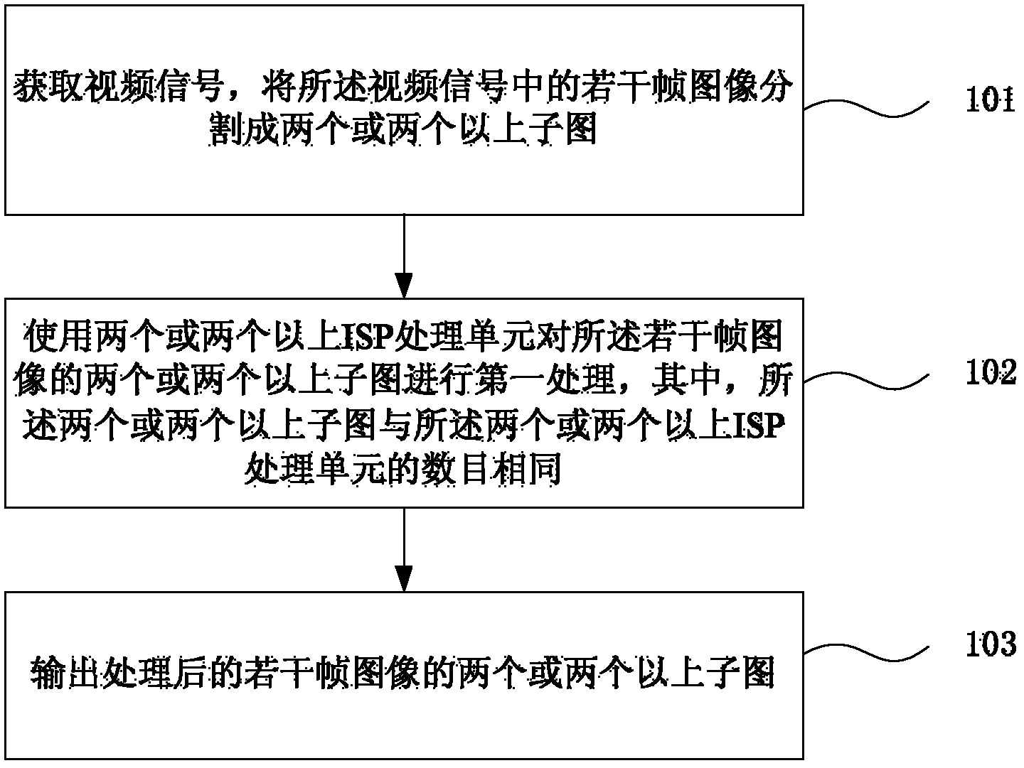
[0028] Figure 1a It is a flowchart of a video signal processing method provided by an embodiment of the present invention. see Figure 1a , the example includes:

[0029] 101. Acquire a video signal, and divide several frames of images in the video signal into two or more subimages;

[0030] The process of acquiring video signals in this step 101 can be realized by an image sensor, preferably, the image sensor is an ultra-high-definition image sensor applied to a single-lens reflex digital camera, for example, can be an AIS (Area Image Sensor, area image sensor), the AIS A plurality of image acquisition elements are arranged in a matrix form inside, and its specific principles and working methods are consistent with those disclosed i...


PUM


Abstract

The invention discloses a video signal processing method and photographic equipment, and belongs to the field of video cameras. The method comprises the following steps of: acquiring a video signal, and dividing a plurality of frames of images in the video signal into two or more than two sub-images; primarily processing the two or more than two sub-images of the plurality of frames of images by using two or more than two image sensor processor (ISP) processing units; and outputting the processed two or more than two sub-images of the plurality of frames of images. The photographic equipment comprises a lens, a sensor, an image divider, a controller and the two or more than two ISP processing units. Image division is used, and the two or more than two ISP processing units are used for performing path division processing on the divided sub-images, so that the resolution of the output images can be improved, image blurring at splicing parts can be avoided, an ultrahigh-definition video camera can be implemented, and the shortcomings of gap overlapping or deficiency, color differences, asynchrony and the like caused by the use of a plurality of video cameras for image splicing in the conventional ultrahigh-definition video camera system are overcome.

Description

technical field [0001] The invention relates to the field of cameras, in particular to a video signal processing method and camera equipment. Background technique [0002] With the development of video technology, people are still pursuing higher video resolution and larger display screens. The telepresence (Teleprence) conference system is the most typical application. The existing technology uses multiple 1920*1080 displays to splice into a larger display, or uses multiple projectors to realize the reality of a high-resolution seamless large screen through fusion technology. Similarly, such an application also requires a super-high resolution camera, and the prior art uses multiple cameras for image splicing to provide a video source of super high resolution. [0003] After analyzing the prior art, the inventor finds that the prior art has at least the following disadvantages: [0004] In the prior art, a plurality of high-definition cameras are generally arranged at a c...

Claims


Application Information

Patent Timeline
Patent Type & Authority Applications(China)
IPC IPC(8): H04N5/14H04N5/262H04N5/232
CPCH04N5/77H04N23/00H04N23/60H04N23/951H04N23/69H04N23/76H04N23/843H04N25/134H04N5/265H04N7/15H04N9/643H04N9/67H04N9/69
Inventor 赵光耀
Owner HUAWEI TECH CO LTD
Why Eureka
Try Eureka