Method for achieving mutual conduction of inner and outer surfaces of plastic component

A technology of inner surface and outer surface, applied in the direction of radiating element structure, chassis/cabinet/drawer parts, antenna grounding switch structure connection, etc.

Active Publication Date: 2012-09-12
SHANGHAI AMPHENOL AIRWAVE COMM ELECTRONICS CO LTD
View PDF4 Cites 18 Cited by
  • Summary
  • Abstract
  • Description
  • Claims
  • Application Information

AI Technical Summary

Problems solved by technology

[0015] The first purpose of the present invention is to provide a method for realizing the mutual conduction between the inner surface and the outer surface of plastic parts, so as to solve the technical problem in the prior art that punching holes with molds needs to be filled with fillers
[0016] The second object of the present invention is to provide a process for making mobile terminal antennas on the casing, so as to solve the technical problem in the prior art that holes need to be filled with fillers when punching holes with molds

Method used


Image

  • Method for achieving mutual conduction of inner and outer surfaces of plastic component
  • Method for achieving mutual conduction of inner and outer surfaces of plastic component
  • Method for achieving mutual conduction of inner and outer surfaces of plastic component

Examples


Embodiment Construction

[0039] see Figure 2A - Figure 2C A method for realizing mutual conduction between the inner surface and the outer surface of a plastic part, comprising the following steps:

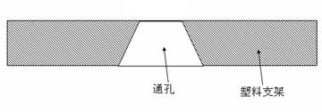
[0040] Drill through holes at predetermined positions of the plastic parts, the diameter of which is about 0.02-0.5MM, preferably, the diameter of the holes is about 0.05-0.3; The method of forming via holes includes at least one of laser drilling, ultrasonic drilling and mechanical drilling.

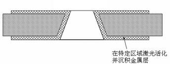
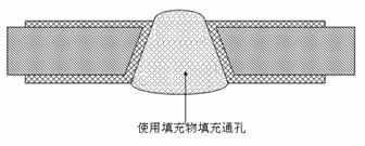
[0041] Activate and deposit the metal layer 12 in a specific area, realize the electrical conduction between the inner surface and the outer surface of the plastic part through the metal layer 12 and do not use fillers to block the hole, the specific area includes at least the inner wall of the hole and the inner surface of the plastic part connected to the inner wall of the hole and the inner surface of the plastic part. outer surface area.

[0042] The holes are generally conical, smaller at one end and larg...


PUM


Abstract

The invention discloses a method for achieving mutual conduction of inner and outer surfaces of a plastic component. The method comprises the following steps of: drilling a through hole at a preset position of the plastic component by using laser; and activating and depositing a metal layer in a specific area to achieve the electric conduction of the inner and outer surfaces of the plastic component. Because the aperture of the through hole is very small, a filler is not required to be filled in the through hole, and the outer surface of the plastic component can be directly coated with a coating layer. Due to the small aperture, the through hole can be directly covered by the coating layer. The through hole is applied to the field, and because the minimum aperture of the through hole can reach 0.02mm, the filler is not required to be filled in the through hole; and therefore, the cost is saved and traces left on the outer surface when the filler is not completely removed and the surface is not well leveled are avoided. The method can be also applied to a production technique for fabricating a mobile terminal antenna onto a shell.

Description

technical field [0001] The invention is applied to the fields of electronic equipment manufacturing, mobile terminals, and multimedia equipment; it can be applied to antennas and other fields where LDS and other metals are attached to the surface of plastic parts as connection lines or decorative effects. Background technique [0002] At present, LDS (LASER DIRECT STRUCTURE, or laser direct structuring) or LSP (LASER SELECTIVE PLATING) or other processes of direct or indirect metal plating on plastic parts are currently performed on plastic parts. [0003] Taking LDS as an example, the LDS technology using a 3D laser system can transfer the CAD data of the antenna design to the model antenna support, or directly to the device structure, such as a mobile terminal cover. The surface of the antenna can also be decorated by a subsequent painting process. LDS technology uses a laser beam to create antenna patterns on the surface of complex three-dimensional parts made of LDS res...

Claims


Application Information

Patent Timeline
Patent Type & Authority Applications(China)
IPC IPC(8): H05K5/02H01Q1/38H01Q1/50
Inventor 陈德智蒋海英郑兵李立忠
Owner SHANGHAI AMPHENOL AIRWAVE COMM ELECTRONICS CO LTD
Why Eureka
Try Eureka