Endoscope

An endoscope and lens technology, applied in the field of endoscopes, can solve problems such as limiting the illumination range, limiting the camera range, and occlusion

Active Publication Date: 2012-09-12
OLYMPUS CORP
View PDF15 Cites 7 Cited by
  • Summary
  • Abstract
  • Description
  • Claims
  • Application Information

AI Technical Summary

Problems solved by technology

[0017] However, in the structure disclosed in International Publication No. WO2006/4083, since the reflector is arranged to protrude outward in the outer diameter direction of the protruding portion, part of the peripheral field of view of the front and side observation combined lens is blocked by the reflector.
Theref

Method used


Image

  • Endoscope
  • Endoscope
  • Endoscope

Examples


no. 1 Embodiment approach )

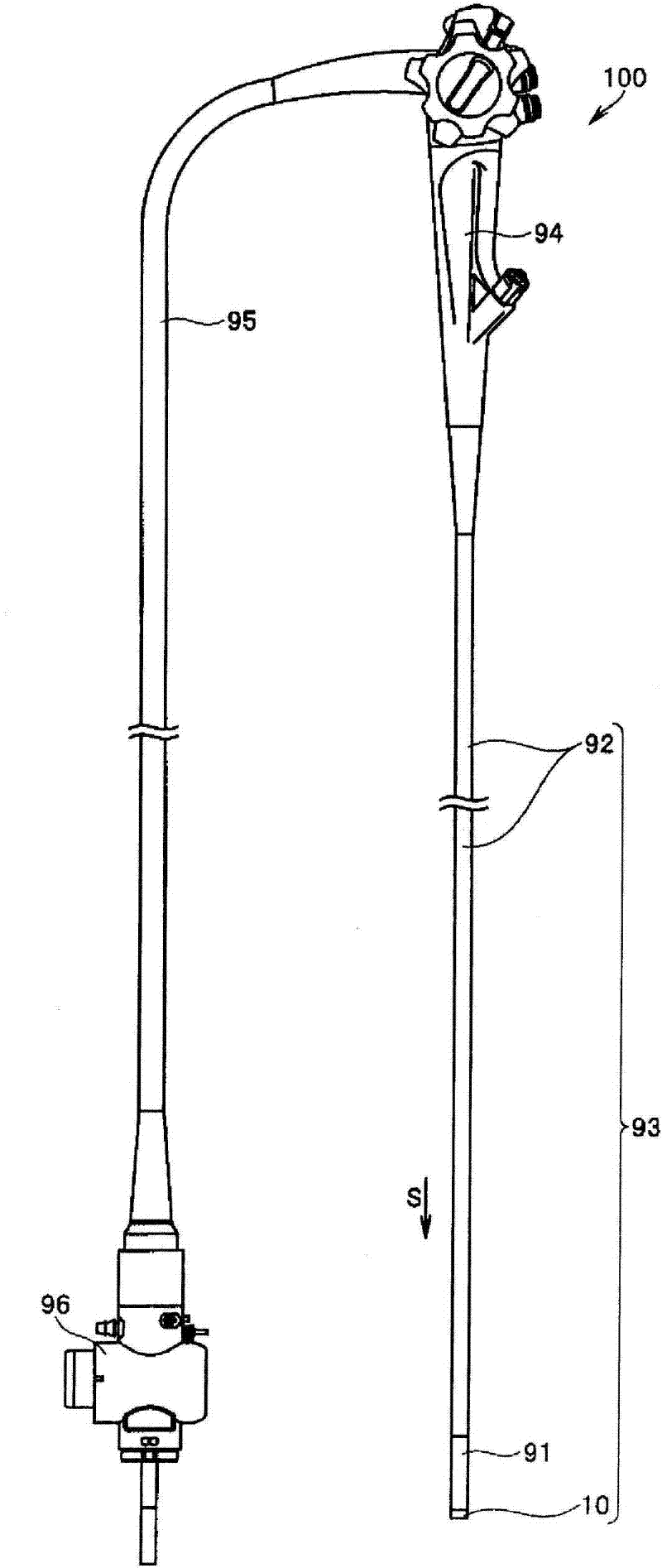
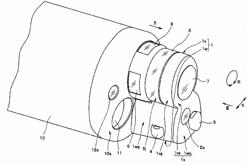
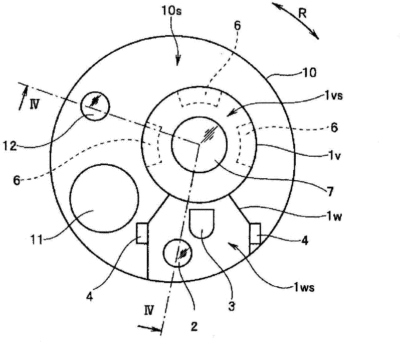
[0064] figure 1 It is a figure showing the outline of the structure of the endoscope of this embodiment, figure 2 is zoomed in figure 1 A partial perspective view of the front end side of the insertion part of the endoscope, image 3 From figure 2 View in the direction of III figure 2 A plan view of the front end side of the insertion part, Figure 4 is along image 3 Partial cross-sectional view of the front end side of the insertion part of the IV-IV line, Figure 5 is shown by figure 1 A diagram of the observation image observed at the insertion portion of the endoscope.

[0065] and then, Figure 32 It is a schematic partial cross-sectional view showing the structure of the distal end side of the endoscope when the region between the side-illuminating lens and the first forward-illuminating lens in the conventional first distal surface is formed as a flat surface.

[0066] and, Figure 33 is shown with Figure 32 Compared with the schematic partial cross-sect...

no. 2 Embodiment approach )

[0112] Figure 6 It is a plan view of the front end side of the insertion part of the endoscope in this embodiment seen from the front, Figure 7 is along Figure 6 A partial cross-sectional view of the front end side of the insertion part along line VII-VII.

[0113] with the above Figure 1 to Figure 5 Compared with the endoscope of the first embodiment shown, the configuration of the endoscope of the second embodiment is different in that the light shielding portion is formed on the lens frame holding the lens for side illumination. Therefore, only the points of difference will be described, and the same reference numerals will be assigned to the same components as those in the first embodiment, and descriptions thereof will be omitted.

[0114] Such as Figure 6 , Figure 7 As shown, in the present embodiment, the side lighting lens 6 is held by the lens frame 30 provided in the first protruding portion 1v, thereby protruding outward in the radial direction K from the...

no. 3 Embodiment approach )

[0122] Figure 8 It is a plan view of the front end side of the insertion part of the endoscope in this embodiment seen from the front, Figure 9 is along Figure 8 A partial cross-sectional view of the front end side of the insertion portion of line IX-IX.

[0123] with the above Figure 6 , Figure 7 Compared with the endoscope of the second embodiment shown, the configuration of the endoscope of the third embodiment is different in that the lens for side lighting is integrally formed with the first lens for front lighting. Therefore, only the points of difference will be described, and the same reference numerals will be assigned to the same configurations as those of the second embodiment, and descriptions thereof will be omitted.

[0124] Such as Figure 8 , Figure 9 As shown, in this embodiment, the side lighting lens 6 and the front end lens 12a of the first front lighting lens 12 are integrally formed as the front and side lighting unit 32 by using the light gui...


PUM


Abstract

An insertion portion, a projecting portion 1 that projects forward from a first distal end surface 10s of the insertion portion, a forward observing lens 7 that is provided to face a second distal end surface 1s of the projecting portion 1, a dual purpose lens 5 that is provided such that a light receiving surface 5j faces an outer peripheral side surface 1vg of the projecting portion 1 along the outer peripheral side surface 1vg of the projecting portion 1, a first forward illuminating lens 12 that is provided to face the first distal end surface 10s,; and a light shielding portion 20m that is located on a phantom line Q that linearly connects an end portion 5t at a distal end side of the dual purpose lens 5 and an end portion 12at at an outer side in a diameter direction K in the first forward illuminating lens 12 and prevents incidence of illumination light emitted from the first forward illuminating lens 12 on a light receiving surface 5j of the dual purpose lens 5, are included.

Description

technical field [0001] The present invention relates to an endoscope having a lens for front observation and a lens for front and side observation. Background technique [0002] In recent years, endoscopes have been widely used in the medical and industrial fields. An endoscope can observe inside a subject by inserting a long and thin insertion portion into the subject. [0003] In addition, as an endoscope, there are known direct-viewing endoscopes in which an observation lens and an illumination lens are provided on the front end surface of the front end portion provided on the front end side of the insertion portion, and on the side surface of the front end portion of the insertion portion. A part of the known side-view endoscope is provided with an observation lens and an illumination lens. [0004] In addition, in recent years, endoscopes have been known that not only can observe the field of view ahead of the front end of the insertion part, but can also observe the ...

Claims


Application Information

Patent Timeline
IPC IPC(8): A61B1/00A61B1/06
CPCA61B1/00091A61B1/00096A61B1/00177A61B1/00181A61B1/0607A61B1/0615G02B23/2423
Inventor 本田一树池田裕一仓康人
Owner OLYMPUS CORP
Why Eureka
Try Eureka