Electronic endoscope and endoscope system

a technology which is applied in the field of electronic endoscope and endoscope system, can solve the problems of limited operation time of wireless electronic endoscope, inconvenient carrying of endoscope system, and obstructive signal cable, so as to prolong the life of the battery of the electronic endoscope and reduce power. , the effect of less power

Inactive Publication Date: 2009-03-26
FUJI PHOTO OPTICAL CO LTD
View PDF7 Cites 7 Cited by
  • Summary
  • Abstract
  • Description
  • Claims
  • Application Information

AI Technical Summary

Benefits of technology

[0017]In the invention, the electronic endoscope includes the first modulation unit that modulates the imaging signal by the first modulation method, the second modulation unit that modulates the imaging signal by the second modulation method, which consumes less power than the first modulation method, and the switching unit that selectively switches between the first modulation unit and the second modulation unit. Thereby, for example, by switching between the first and second modulation methods so that the second modulation method may be selected during insertion and pull-out of the insertion part and the first modulation method may be selected only during observation, electric power can be saved, and the life of the battery of the electronic endoscope can be prolonged.
[0018]Furthermore, by detecting the voltage of the battery, and if the voltage becomes equal to or lower than the predetermined value, then modulating the imaging signal by the second modulation method, which consumes less power, it becomes possible to set the threshold of the voltage to a value at which battery exhaustion may immediately occur if the first modulation method is kept used. Thus, the capacity of the battery can be efficiently utilized. Furthermore, the operating time of the electronic endoscope within the body cavity becomes long as power consumption decreases. As a result, it is possible to gain time enough to pull out the insertion part in the body cavity. Thus, the battery exhaustion during observation can be prevented.

Problems solved by technology

In such an endoscope system, there is a problem that the signal cable might become obstructive when the electronic endoscope is operated, and / or that it might be inconvenient to carry the endoscope system.
For this reason, a battery is used in the wireless electronic endoscope as a power source, and an operating time of the wireless electronic endoscope is limited.
In this case, short operating time of the electronic endoscope becomes a cause which degrades maintenance properties, for example, replacement or charge of the battery should be performed frequently.
Furthermore, in the wireless electronic endoscope which uses the battery as a power source, battery exhaustion may unexpectedly occur during use.
If the battery exhaustion occurs in a state where the insertion part is in the body cavity of a person being tested, an image cannot be confirmed when the insertion part is pulled out.
Therefore, there is concern that the body cavity of the person being tested might be damaged by the tip end of the insertion part, etc.
In this case, if there is no margin for the threshold, the battery exhaustion might occur while the insertion part is being pulled out from the body cavity.
However, giving excessive margin to the threshold might cause that the battery is determined as being exhausted while its capacity is left relatively much.
As a result, there is a concern that the capacity of the battery cannot be efficiently utilized, and that the operating time of the electronic endoscope may be vainly shortened.

Method used


Image

  • Electronic endoscope and endoscope system
  • Electronic endoscope and endoscope system
  • Electronic endoscope and endoscope system

Examples


Embodiment Construction

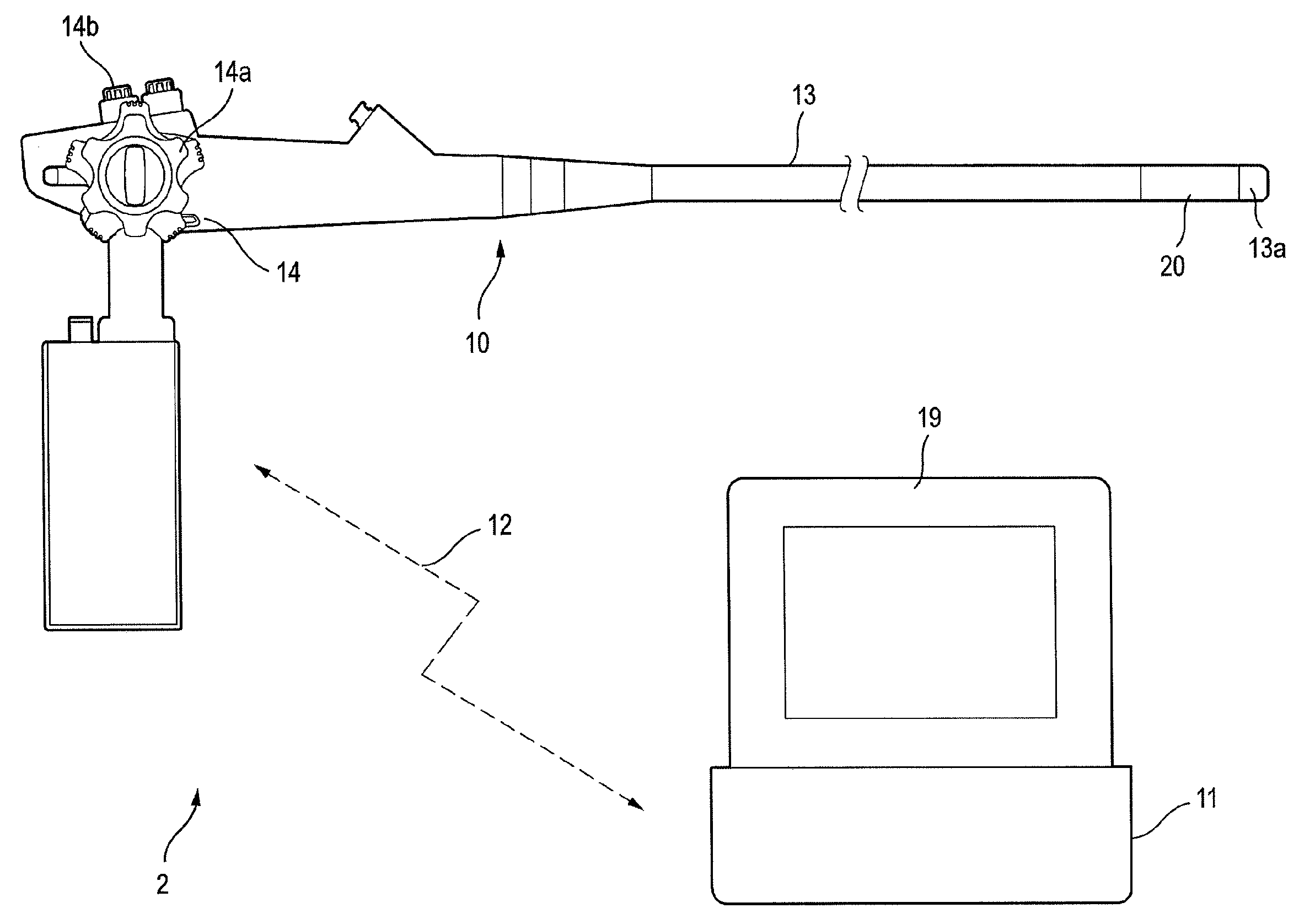
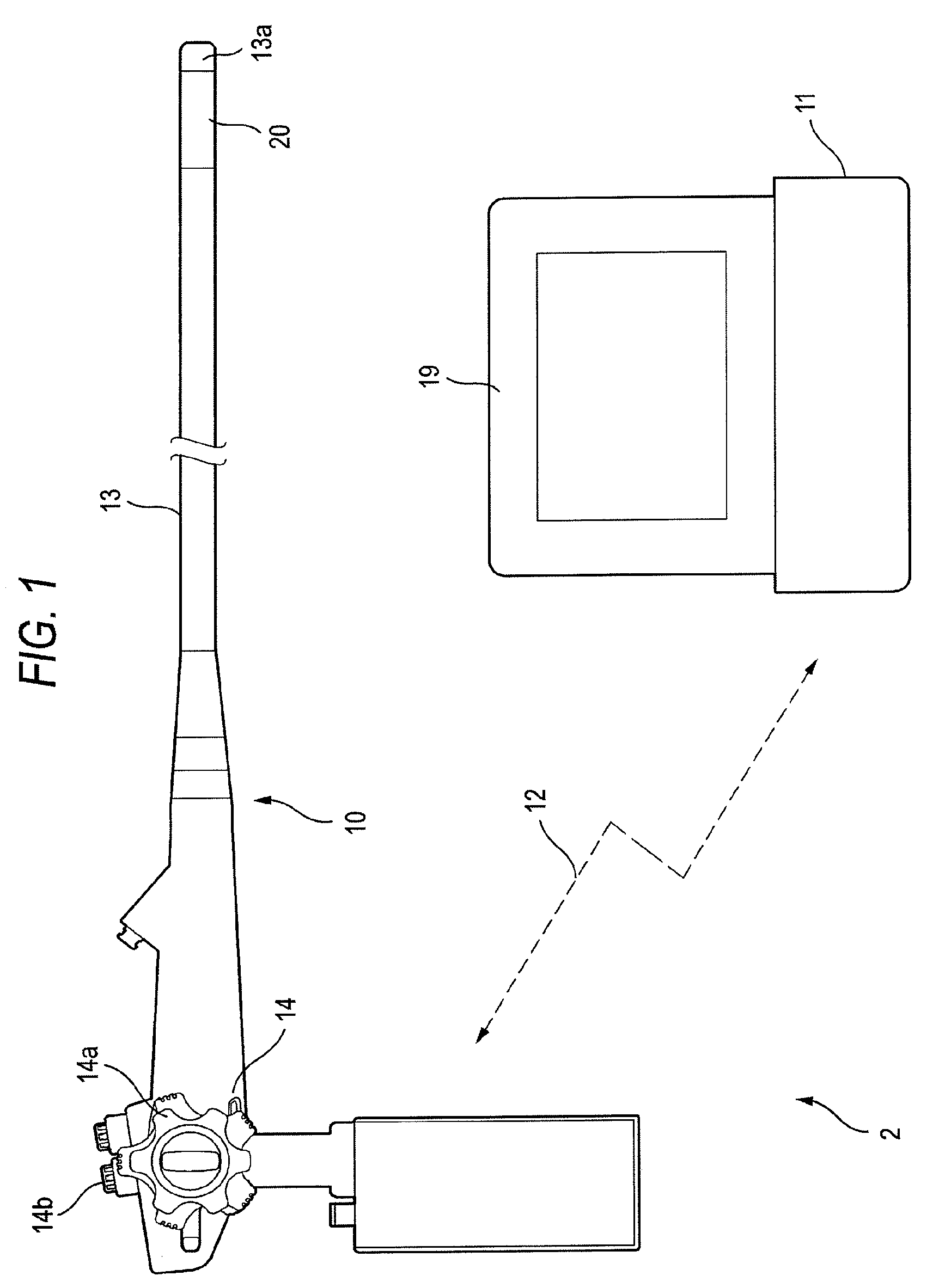
[0024]As shown in FIG. 1, an endoscope system 2 includes an electronic endoscope 10 and a processor device 11. The endoscope system 2 is a so-called wireless endoscope system which exchanges a signal between the electronic endoscope 10 and the processor device 11 by an electric wave 12.

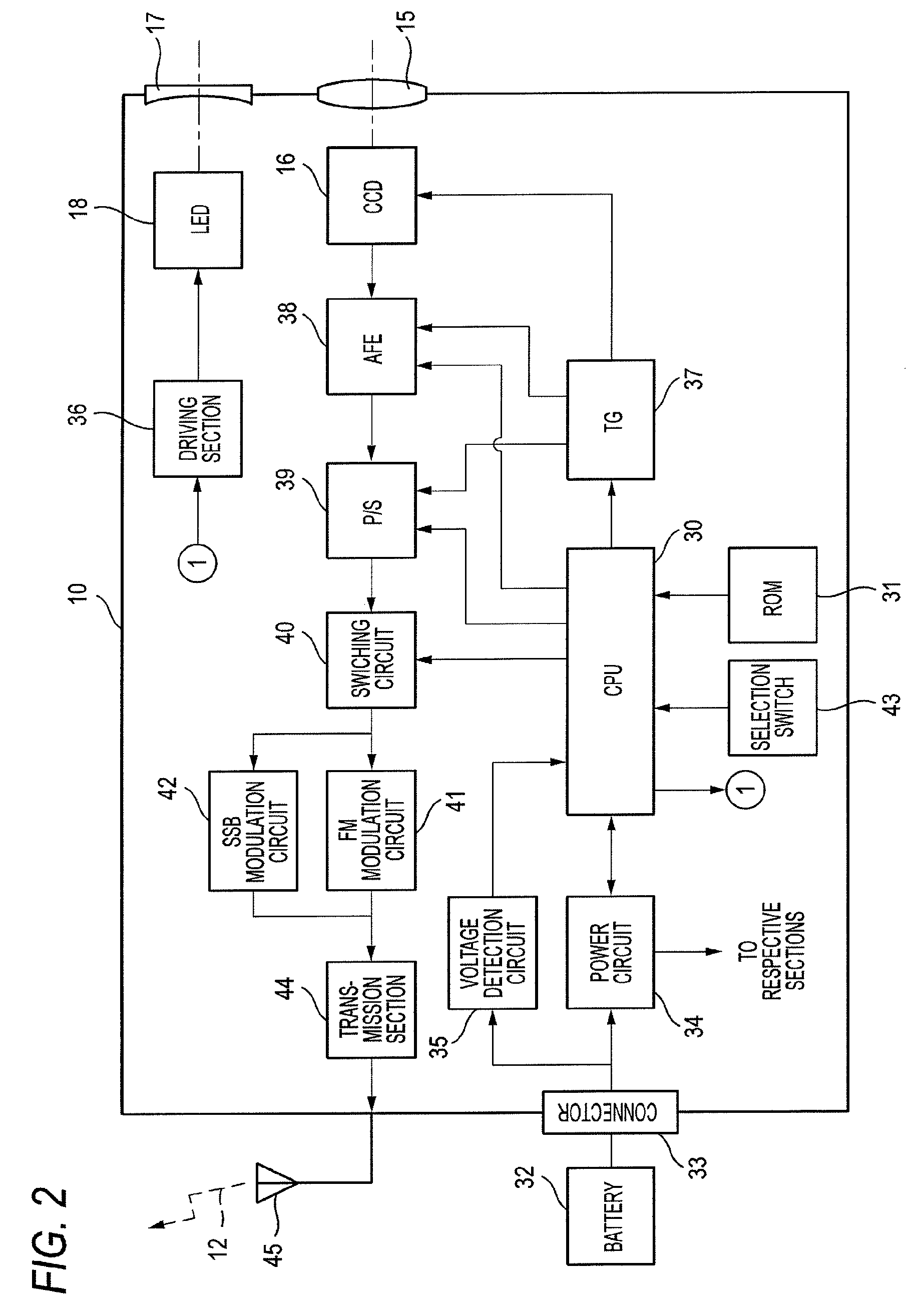
[0025]The electronic endoscope 10 includes an insertion part 13, which has a narrow tube shape and is configured to be inserted into a body cavity, and an operating part 14 connected to a base end of the insertion part 13. The tip end part 13a of the insertion part 13 includes therein an objective lens 15 for captures image light of an image of an observed object in a body cavity, a CCD 16 (for example, pixel size: 1280×960, frame rate: 30 frames / second) as an imaging device which images an observed body within the body cavity, an illumination lens 17, and an LED 18 for illuminate an inside of the body cavity (see FIG. 2 about all of them). An image within the body cavity acquired by the CCD 16 is dis...


PUM


Abstract

An electronic endoscope 10 is provided with an FM circuit 41 and an SSB modulation circuit 42. Electric power is supplied to the electronic endoscope 10 from a battery 32. The battery 32 is connected to a voltage detection circuit 35. The voltage detector 35 detects a voltage of the battery 32 and inputs the detected voltage to a CPU 30. The CPU 30 determines as to whether or not the voltage of the battery 32 is equal to or lower than a predetermined value. If the CPU 30 determines that the voltage is equal to or lower than the predetermined value, the CPU 30 causes the SSB modulation circuit 42, which consumes less power, to modulate image data.

Description

CROSS-REFERENCE TO RELATED APPLICATIONS[0001]This application is based upon and claims the benefit of priority from the Japanese Patent Application No. 2007-248750 filed on Sep. 26, 2007; the entire contents of which are incorporated herein by reference.BACKGROUND OF THE INVENTION[0002]1. Technical Field[0003]The invention relates to a wireless electronic endoseope that wirelessly transmits acquired imaging signals, and an endoscope system using the electronic endoscope.[0004]2. Description of the Related Art[0005]In the medical field, medical diagnosis is performed using an electronic endoscope. The electronic endoscope has an imaging device, such as a CCD, built in the tip end of an insertion part which is configured to be inserted into a body cavity. Imaging signals acquired by the CCD are converted into digital image data by various kinds of signal processing, and are then input to a processor device. The processor device further performs signal processing, etc. for the input im...

Claims


Application Information

Patent Timeline
Patent Type & Authority Applications(United States)
IPC IPC(8): H04N7/18
CPCA61B1/05A61B1/00016
Inventor ABE, KAZUNORI
Owner FUJI PHOTO OPTICAL CO LTD
Why Eureka
Try Eureka