
Disc brake

A disc brake, brake cylinder technology, applied in the direction of brakes, brake types, brake components, etc.

Active Publication Date: 2012-09-12
KNORR-BREMSE SYST FUER NUTZFAHRZEUGE GMBH
View PDF5 Cites 3 Cited by
  • Summary
  • Abstract
  • Description
  • Claims
  • Application Information

AI Technical Summary

Problems solved by technology

[0003] On the flange of the brake caliper, other functional components are usually fastened next to the brake cylinder, thus limiting the installation space for the installation possibilities of the brake cylinder or other functional components to be installed

Method used


Image

  • Disc brake
  • Disc brake
  • Disc brake

Examples


Embodiment Construction

[0015] In the following description of the figures, concepts like up, down, left, right, front, rear etc. relate only to the exemplary representation and position of disc brakes and other objects selected in the respective figures. These concepts are not to be understood as limiting, ie these relationships can vary due to different working positions or mirror-symmetrical designs, etc.

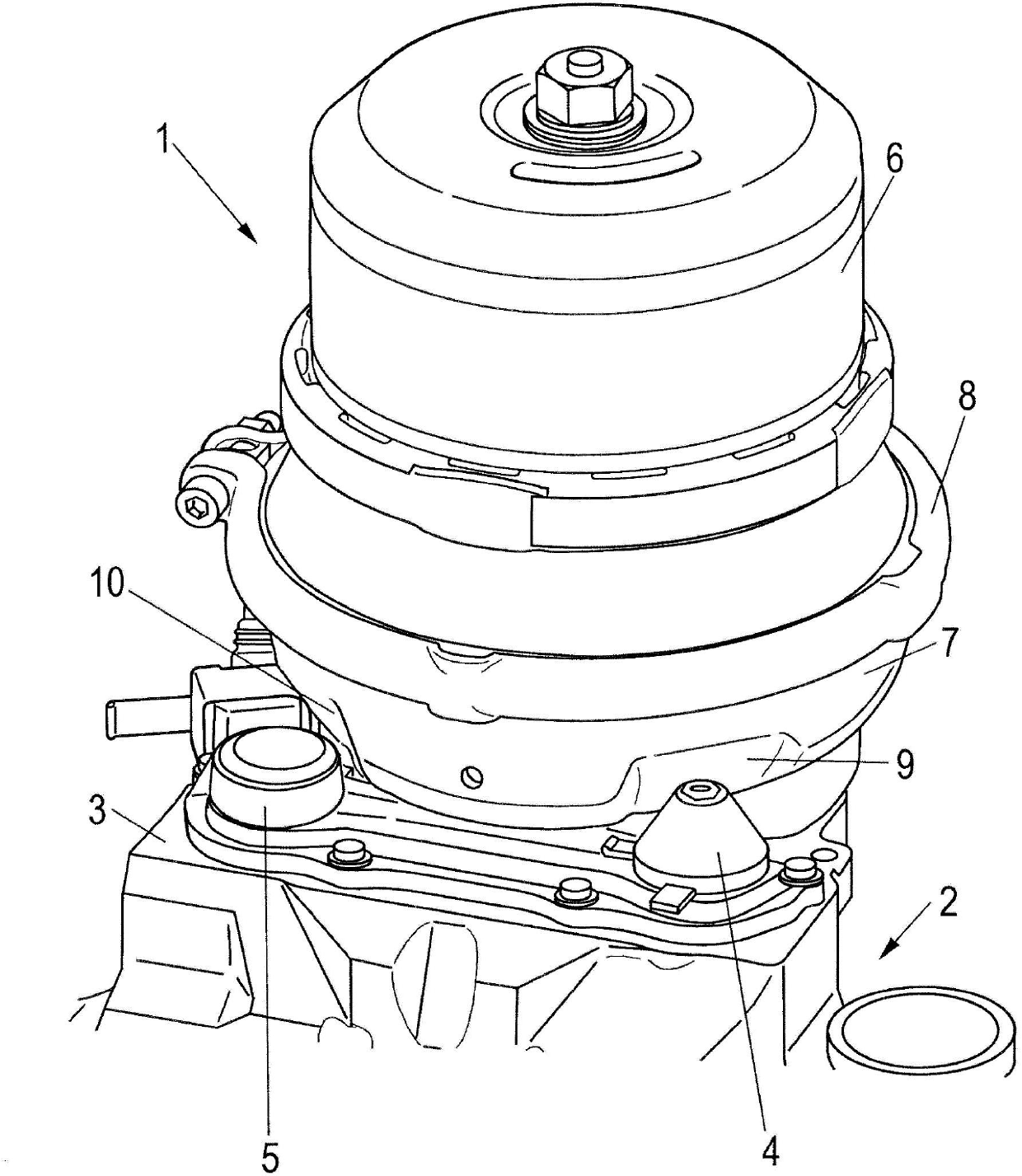
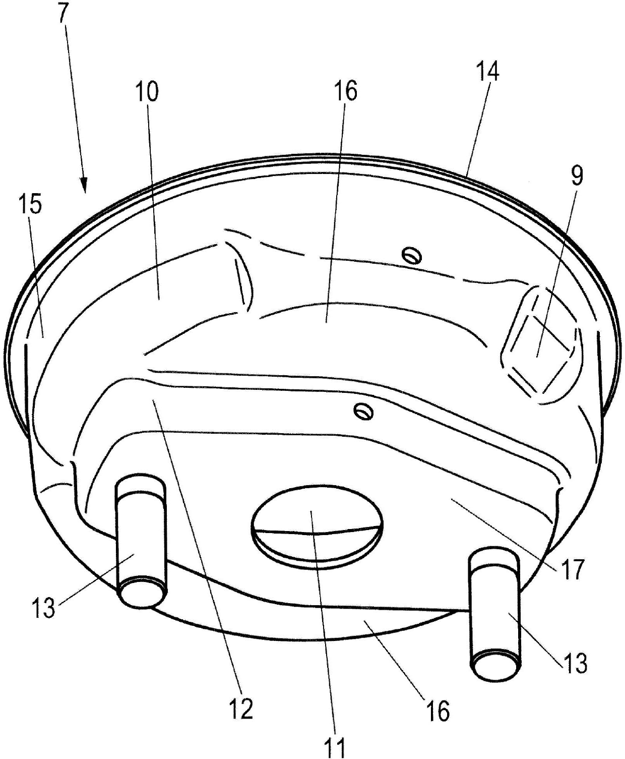
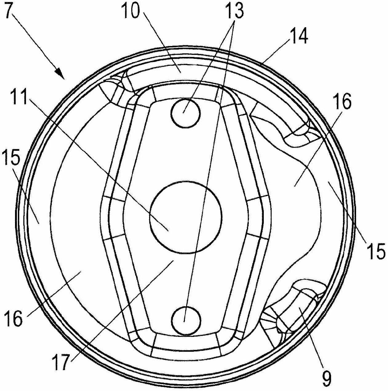
[0016] exist figure 1 , the brake cylinder is marked with reference numeral 1 as a whole, and the brake cylinder is fixed on the flange 3 of the brake caliper 2 . Brake cylinder 1 has a housing 6 , 7 which is preferably formed in two parts, wherein the two housing parts 6 , 7 are held together or crimped to one another by a tensioning strap 8 . The two housing parts 6 , 7 are pot-shaped, wherein the outer peripheral surfaces of the housings 6 , 7 have flanges 14 on the edges facing each other, which flanges 14 can be enclosed by the tensioning strap 8 .

[0017] The brake cylinder 1 is prefer...


PUM


Abstract

The invention relates to a pneumatically actuable disc brake comprising a brake caliper (2) extending over a brake disc, wherein a brake cylinder (1), to which compressed air can be applied, and at least one further functional part (4, 5) are fastened on a flange (3) of the brake caliper (2), wherein the brake cylinder (1) is provided with at least one indentation (9, 10) at least in the overlapping region with the at least one functional part (4, 5).

Description

technical field [0001] The invention relates to a pneumatically actuated disc brake according to the preamble of claim 1 . Background technique [0002] Such a pneumatically actuated disc brake is known, for example, from DE 10 2008 004 896 A1 or DE 10 2006 010 215 B3. In this case, a brake cylinder, which can be acted upon with compressed air, is attached as a brake force generator to the flange of the brake caliper. [0003] On the flange of the brake caliper, other functional components are usually fastened next to the brake cylinder, so that the installation space for the installation possibilities of the brake cylinder or other functional components to be installed is thus limited. Contents of the invention [0004] It is therefore the object of the present invention to further improve a pneumatically actuated disc brake in such a way that the installation space is optimized and the functional parts mounted on the brake caliper are easily accessible. [0005] This o...

Claims


Application Information

Patent Timeline
Patent Type & Authority Applications(China)
IPC IPC(8): F16D65/14B60T17/08
CPCB60T17/088F16D65/18F16D2121/02F16D2125/28B60T17/08F16D65/095F16D65/14
Inventor 西尔万·德劳奥尔特斯特凡娜·埃里舍尔
Owner KNORR-BREMSE SYST FUER NUTZFAHRZEUGE GMBH
Learn More