Compact multispectral scanning system

一种多光谱扫描、扫描系统的技术,应用在光学、光学元件、仪器等方向,能够解决不能用检测器、信噪比恶化等问题

Inactive Publication Date: 2012-09-12
ALFA IMAGING
View PDF7 Cites 41 Cited by
  • Summary
  • Abstract
  • Description
  • Claims
  • Application Information

AI Technical Summary

Problems solved by technology

The first disadvantage is that it cannot be used with a certain range of detectors (visible light, infrared, millimeter wave, terahertz wave, etc.), but only one frequency band
The second disadvantage is the deterioration of the signal-to-noise ratio mainly due to the transmission loss inherent in the quarter-wave plate

Method used


Image

  • Compact multispectral scanning system
  • Compact multispectral scanning system
  • Compact multispectral scanning system

Examples


Embodiment Construction

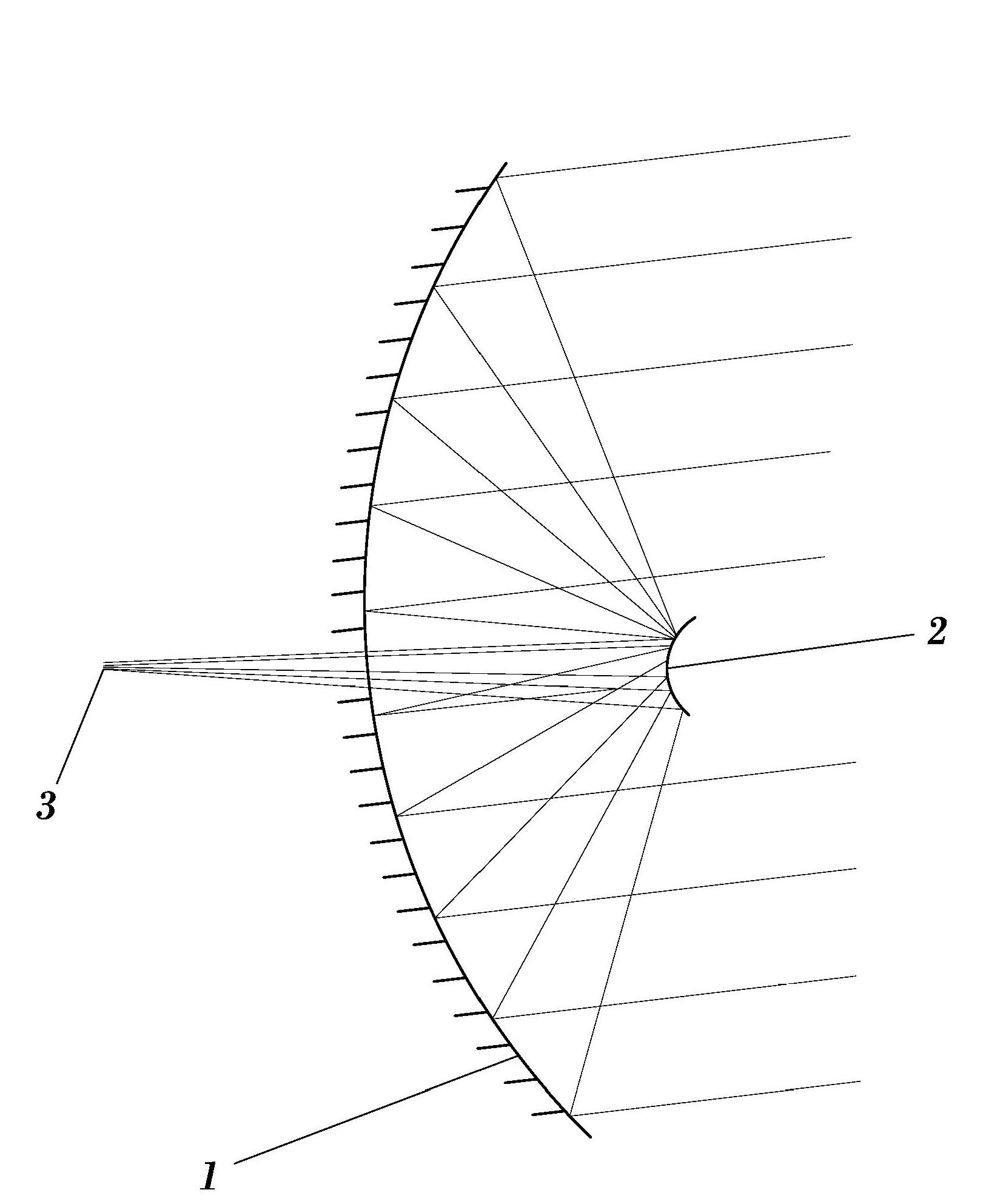
[0022] figure 1 An embodiment of the invention is shown where the detector is placed behind the primary mirror. The primary mirror (1) is concave while the secondary mirror (2) is convex. The radiation is collected at the focal point (3) where the detector is located on axis behind the primary mirror. Without being considered a limitation of the invention, this embodiment is designed to facilitate the incorporation of single pixel detectors and / or radar transceivers or lidar or lidar systems.

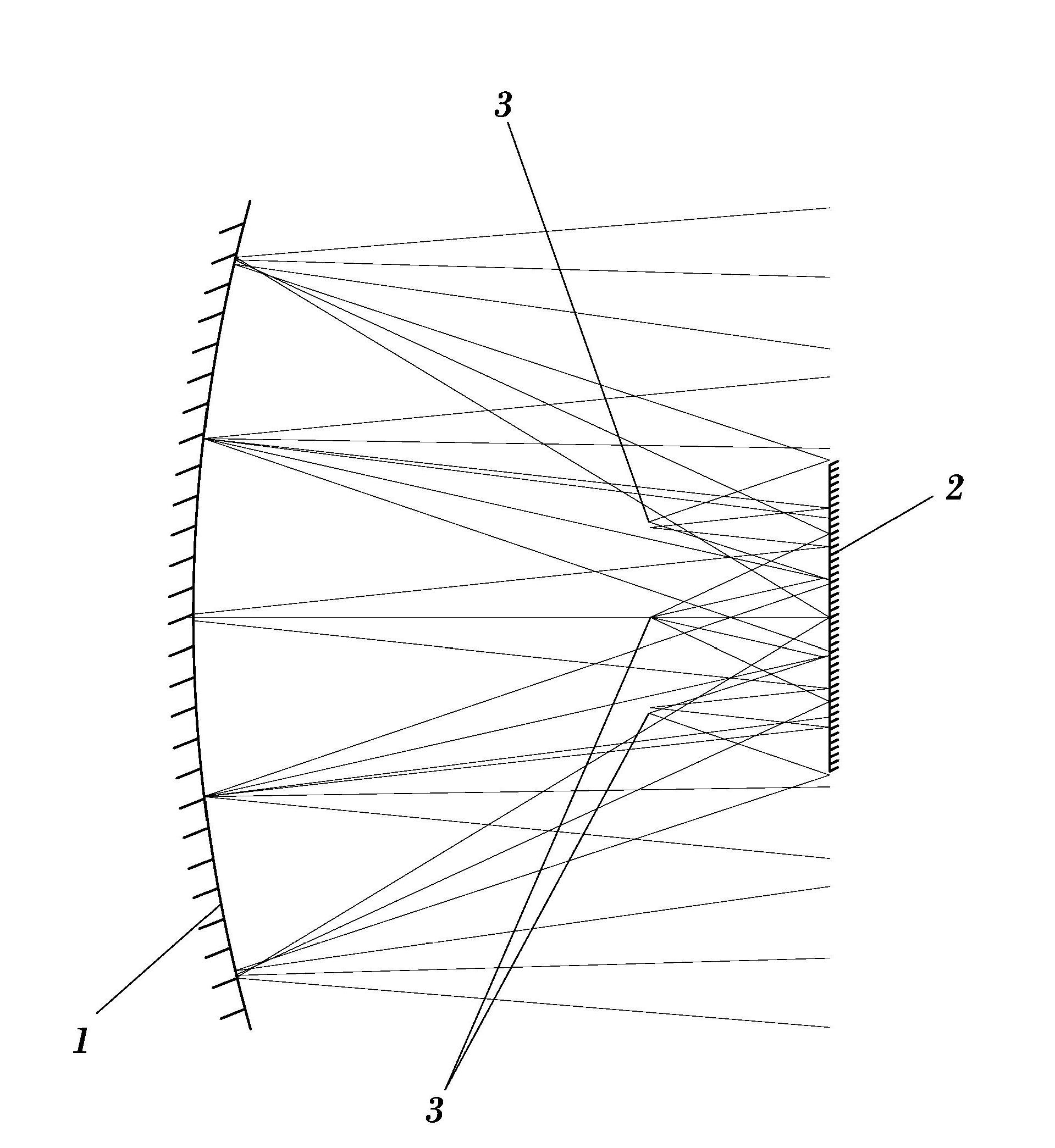
[0023] figure 2 An embodiment of the invention is shown where the detector is placed between two mirrors. In this case, the primary mirror (1) is concave, while the secondary mirror (2) is planar. This other possible embodiment is designed for a system using a bank of detectors and their corresponding antennas. By placing a row of detectors in the focal plane, the system covers a field of view (in the same direction) that is proportional to the length of the row of detectors, alth...


PUM


Abstract

The invention refers to a compact multispectral scanning system comprising a primary mirror (1) and secondary mirror (2), wherein the mirrors face each other, are adapted to be rotated at the same angular speed in opposite directions, and are tilted with respect to their rotation axes. The primary mirror is concave, the secondary mirror is smaller than the primary mirror and the rotation axes of both mirrors are aligned. This arrangement makes the system more compact than prior art devices and avoids the dependency of the system on the operation frequency.

Description

technical field [0001] The present invention relates to the field of optical engineering, and in particular to the field of scanning imaging systems. The scanning system of the present invention is intended to be capable of operating at a frame rate sufficient to be considered real-time and over a broad wavelength range including millimeter waves, terahertz waves, infrared waves, microwaves and x-rays. Background technique [0002] A desired requirement in any scanning imaging system is to scan the scene in a linear pattern and at the highest possible speed. A simple way of achieving this is by means of moving plane mirrors. Various mirror-based solutions exist, among which are found flipping mirrors (only one face) moved by means of different mechanisms (eg galvanometer type), or rotating polyhedrons with multiple mirrored faces . These techniques are used in systems operating at small wavelengths such as infrared and visible wavelengths. [0003] In infrared systems, t...

Claims


Application Information

Patent Timeline
Patent Type & Authority Applications(China)
IPC IPC(8): G02B17/06G02B26/10
Inventor 卡洛斯·卡列赫罗安德烈斯
Owner ALFA IMAGING
Why Eureka
Try Eureka