

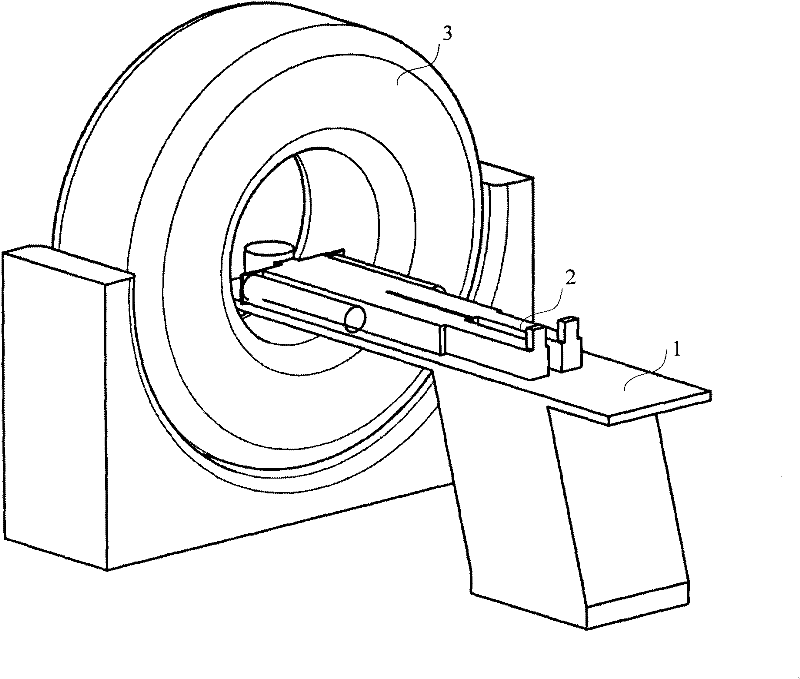
Computed tomography (CT) machine
A frame and motor-driven technology, applied in computerized tomography scanners, echo tomography, etc., can solve the problems of increasing patient radiation dose, inaccurate imaging, and impact, and achieve the effect of reducing costs and reducing radiation damage
- Summary
- Abstract
- Description
- Claims
- Application Information
AI Technical Summary
Problems solved by technology
Method used
Image

Examples
Embodiment Construction
[0035] In order to make the purpose, technical solution and advantages of the present invention clearer, the following examples are given to further describe the present invention in detail.
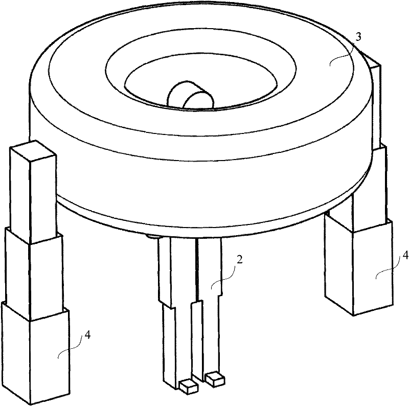
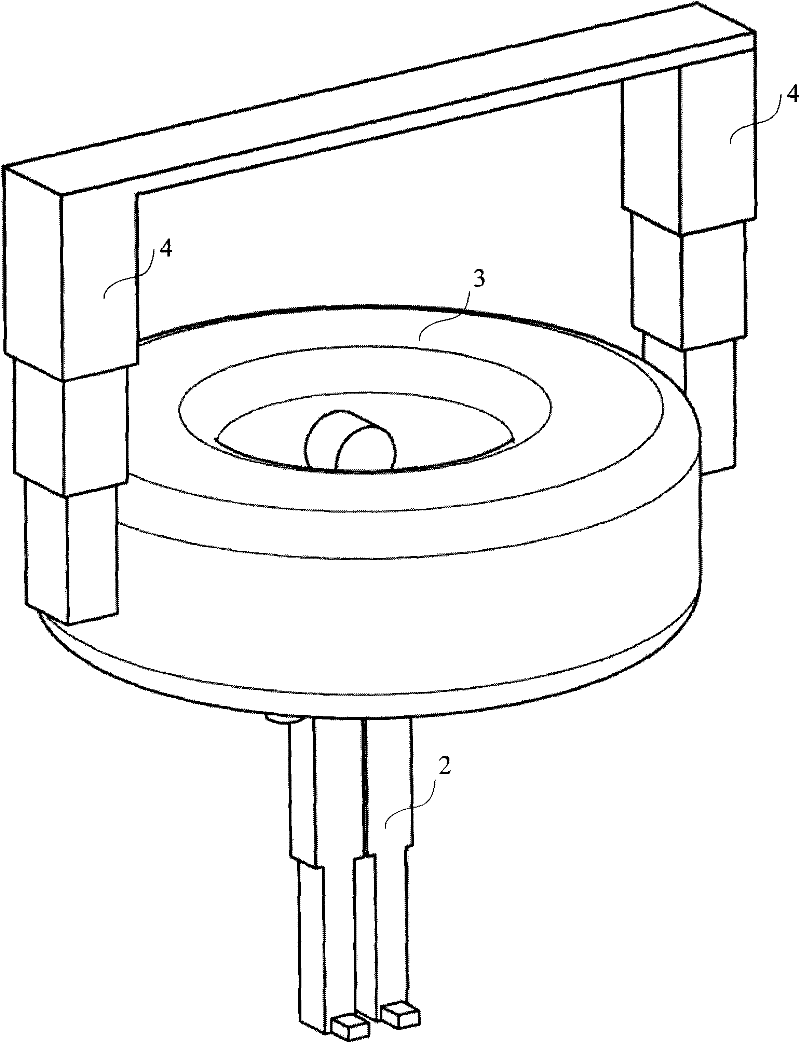
[0036] figure 2 It is a partial structural schematic diagram of a CT machine in an embodiment of the present invention. image 3 It is a partial structural schematic diagram of a CT machine in another embodiment of the present invention.
[0037] like figure 2 and image 3 As shown, the CT machine in the embodiment of the present invention mainly includes: a CT frame 3, a vertical lifting mechanism (not shown in the figure), and a linear guide mechanism 4 that is used vertically and has a fixed position.
[0038] Wherein, the CT frame 3 is installed on the vertical lifting mechanism in a manner that the scanning plane is parallel to the ground or approximately parallel to the ground, and the vertical lifting mechanism can drive the CT frame 3 to carry out vertical lifting movement, ...
PUM
 Abstract
Description
Claims
Application Information